







 Tweet
Tweet
 Super Pilot Lamp
This is my 1st thread, Hope you people will like it .
Super Pilot lamps -
3W LEDs , running with 800mA constant current regulator . along with Collimator lens .
Things you need to do it .
1. 3W LEDs . the best you can find is CREE but they are expensive.One can use local too.
2.star type Heatsink for the LEDs
3.Bigger Heatsink To cool the LEDs
4. Constant Current regulator (variable ones are most welcome) . You can make yourself one or you can buy one online .
5. Heat conductive paste, or glue
5.Miscellaneous - some wires , a small plastic box to house the controller ,Heat gun to open the glass from the reflector , soldering iron . etc etc .
To do this u must have good knowledge about electrical & electronics with good skill of soldering .
The Bike must be Full DC configured .
This is the Collimator Lens

To make this you need to open the Glass from the reflector using heat gun

This the stock hole for pilot lamps .

After fitting the collimator lens, hold that with hand & check if the LED seats there perfectly or not .
then use Feviquik to fix that lens in place .

I have This heatsink lying around my workplace . U should use similar ones .

Later I cut that Heatsink like this to properly mount the LEDs

Now place the heatsink over the LED to take measurements of where to place the LED on the heatsink & mark that

Use heat conductive compound or glue to seat the LEDs on the heatsink

Now use Feviquik to Fix everything in place, & if you have used Heat glue then no need to put FeviquiK . one can put screws to fix them in place too

Now Put whole thing in place Check every thing. & Don't forget to use hot glue to secure everything in place . again one can use bracket or similar if they need to

Now Comes the controller part, I Used this controller . It uses L200 . The LEDs are connected in series connection with the output . Never Use any high power LEDs in parallel connection directly. If you have to use them in parallel then use proper resistor in series with the LEDs.
This Regulator can take as high as 30V as input , so it's very safe to use in automotive application

After soldering the circuit in general purpose PCB bord , it looks like this .

Now you need some kind box to house the controller. I have some clear acrylic sheet lying around, so i cut them & made this box .
U can make ur own or buy suitable one

Now the moment of truth. connect the input of the controller with any 12V battery or wall adapter capable of providing 2A at 12V & check the output .

Now place every thing in your bike & test run .
This is how it looks from the front . This picture is taken with flash, so u can understand how much bright it is .


Connection of the pilot lamp varies from bike to bike , as they all have different color wires but in RTR , the +ve to be connected to the controller is grey wire & -ve is black wire with white stripe . Or simple the bike's frame .
Super Pilot lamps -
3W LEDs , running with 800mA constant current regulator . along with Collimator lens .
Things you need to do it .
1. 3W LEDs . the best you can find is CREE but they are expensive.One can use local too.
2.star type Heatsink for the LEDs
3.Bigger Heatsink To cool the LEDs
4. Constant Current regulator (variable ones are most welcome) . You can make yourself one or you can buy one online .
5. Heat conductive paste, or glue
5.Miscellaneous - some wires , a small plastic box to house the controller ,Heat gun to open the glass from the reflector , soldering iron . etc etc .
To do this u must have good knowledge about electrical & electronics with good skill of soldering .
The Bike must be Full DC configured .
This is the Collimator Lens
To make this you need to open the Glass from the reflector using heat gun
This the stock hole for pilot lamps .
After fitting the collimator lens, hold that with hand & check if the LED seats there perfectly or not .
then use Feviquik to fix that lens in place .
I have This heatsink lying around my workplace . U should use similar ones .
Later I cut that Heatsink like this to properly mount the LEDs
Now place the heatsink over the LED to take measurements of where to place the LED on the heatsink & mark that
Use heat conductive compound or glue to seat the LEDs on the heatsink
Now use Feviquik to Fix everything in place, & if you have used Heat glue then no need to put FeviquiK . one can put screws to fix them in place too
Now Put whole thing in place Check every thing. & Don't forget to use hot glue to secure everything in place . again one can use bracket or similar if they need to
Now Comes the controller part, I Used this controller . It uses L200 . The LEDs are connected in series connection with the output . Never Use any high power LEDs in parallel connection directly. If you have to use them in parallel then use proper resistor in series with the LEDs.
This Regulator can take as high as 30V as input , so it's very safe to use in automotive application
After soldering the circuit in general purpose PCB bord , it looks like this .
Now you need some kind box to house the controller. I have some clear acrylic sheet lying around, so i cut them & made this box .
U can make ur own or buy suitable one
Now the moment of truth. connect the input of the controller with any 12V battery or wall adapter capable of providing 2A at 12V & check the output .
Now place every thing in your bike & test run .
This is how it looks from the front . This picture is taken with flash, so u can understand how much bright it is .
Connection of the pilot lamp varies from bike to bike , as they all have different color wires but in RTR , the +ve to be connected to the controller is grey wire & -ve is black wire with white stripe . Or simple the bike's frame .
Attached Files

 . u can find every thing there .
 . show them this photo for reference in case they dont understand what u are asking for .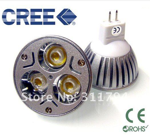





Comment