Since '02 xBhp is different things to different people. From a close knit national community of bikers to India's only motorcycling lifestyle magazine and a place to make like-minded biker friends. Join us

Castrol Power 1

Learn & practice evasive maneuvers.

Our Partner

Announcement

Collapse
No announcement yet.

Making of Kawasaki Ninja 300 San

Collapse
X
 
  • Filter
  • Time
  • Show
Clear All
new posts

  • #46
    Installation of All Balls Tapper Roller Bearings

    Installation of All Balls Tapper Roller Bearings

    After having changed the stock wheels to ultra lightweight Brembo Marchesini (detailed in previous posts) it became necessary to upgrade the suspension to account for the reduced un-sprung weight.

    After considering all the options available to us, we came up with a detailed game plan for making the required changes. Considering the deficit of height difference (detailed in the post for wheel change) created by using Metzelers, we decided that the front suspension assembly needs to be attended to first in order to address this deficit.

    Considering all the pros and cons we have decided to change the complete internals of the fork and convert the stock damper type fork to cartridge one. The forks will have custom made springs and dampening rates, which take into account the reduced un-sprung weight, my weight, riding style, etc.

    However, before we start working on the forks it was necessary to address the weakest link in the whole front assembly i.e. bearings for steering cone set. We decided to install tapper roller bearings in lieu of the stock ball bearings. There is nothing wrong with my stock steering cone set. It is working just fine. However, the steering cone set is another part where the bean-counting accountants have made their presence felt. While ball bearing type cone set is a cheaper option, which gets the work done, it is not the best of solutions.

    In the ball bearing solution the loads are applied radially to the balls and race cup thus creating highly concentrated load spots on the balls. While this works just fine under most conditions, they tend to fail early compared to other solutions. Most of you will have replaced the cone set of your bikes within a couple of years of buying your bike. I suspect many of you may have done this within months of getting your bikes.

    The problem with the ball bearing application is that while the radial loads are taken care of by the bearings, they combine with axial loads that create flex and twisting loads on the ball and race cups.

    Click image for larger version

Name:	ball_bearing_diag.gif
Views:	1
Size:	4.0 KB
ID:	1882597
    Typical Ball Bearing. Note the contact area between the balls and the races.

    Click image for larger version

Name:	459px-Thrust-ball-bearing_din711_ex.jpg
Views:	1
Size:	16.4 KB
ID:	1882598
    Example of thrust type ball bearing used in stock steering cone set.Click image for larger version

Name:	1000f08_tcm_12-4316.gif
Views:	1
Size:	4.3 KB
ID:	1882599
    Cutaway of tapper roller bearing. Note the enhanced load area vis-a-vis the ball bearing above.


    Therefore, considering the above factors we thought it prudent to improve and strengthen the weakest link in the front assembly.

    The other problem that most of us face after replacing the steering cone set is the fact that it never feels like the original fitting. This due to the fact that during production, the chassis is completely bare and the races of the cone set are installed with jigs and fixtures with the correct amount of recommended force. However, when installation is done at the service center no jigs or fixtures are used. Many a times I have seen races being hammered into the chassis. Without fail this gives me a near heart attack to see such abuse being done to something so crucial. Whenever, I speak to so called service engineers, I get a blank look and a standard reply, “This is how it is always done!” Bearing installation is a science and not a hatchet job. Check any of the ball bearing manufactures website and you will find elaborate instructions on how their bearings should be fitted. I shared my concerns with Vikram of Motozone. He assured me that the mounting of the bearings will be done with proper jigs and fixtures and correct amount of force will be applied at all times during installation. Even if he did not have right fixture, he would make one before starting the work. He also showed me the special hydraulic press that he had for such applications.

    Thus started the hunt of tapper roller bearings. We started looking for bearings from reputed manufactures like SKF, Timken, NMB, etc. However, it seemed that none of these manufactures had the bearings with the required dimensions. After a fruitless search, we came upon a small company called All Balls Bearings in the U.S. that specially manufactures bearings for conversions like the Ninja 300. Therefore, a set of tapper roller bearings were ordered from All Balls Bearings.

    Click image for larger version

Name:	DSC_0044.jpg
Views:	1
Size:	100.3 KB
ID:	1882600
    The All Balls Bearings packing.

    Click image for larger version

Name:	DSC_0045.jpg
Views:	1
Size:	100.7 KB
ID:	1882601
    Contents of the packing. 2 sets of bearings and dust covers.

    Click image for larger version

Name:	IMG-20140516-WA0021.jpg
Views:	1
Size:	94.3 KB
ID:	1882602
    The bearings, races and dust covers.

    Click image for larger version

Name:	IMG-20140516-WA0022.jpg
Views:	1
Size:	63.3 KB
ID:	1882603
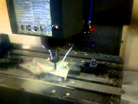
    The lower bearing being mounted on to the steering stem and lower triple clamp. Note the hydraulic press used to ensure that even pressure is applied across the race collar while mounting the bearing.

    Click image for larger version

Name:	IMG-20140516-WA0023.jpg
Views:	1
Size:	61.5 KB
ID:	1882604
    Measurements were carried out at various points of the installation to ensure that the mounting of the bearing is within specified parameters.

    Click image for larger version

Name:	IMG-20140516-WA0020.jpg
Views:	1
Size:	74.1 KB
ID:	1882605
    The outer race of the lower bearing being mounted into the steering stem with the hydraulic press.

    Click image for larger version

Name:	IMG-20140519-WA0002.jpg
Views:	1
Size:	54.7 KB
ID:	1882606
    Measurements being taken of the installed outer race.

    Click image for larger version

Name:	IMG-20140516-WA0025.jpg
Views:	1
Size:	72.9 KB
ID:	1882607
    Similarly the upper bearing outer race after installation.

    Click image for larger version

Name:	IMG-20140519-WA0001.jpg
Views:	1
Size:	82.2 KB
ID:	1882608
    Installation of the bearings completed. The complete installation took 8 hours!

    Another interesting thing that was found was the misalignment of the forks. Kawasaki recommends that the forks be 10 millimetres above the upper triple clamp i.e. the distance from the top of the fork to the top surface of the top triple clamp should be 10 mm. Much to our surprise we found that the left fork was 9 mm whereas the right one was 10 mm. That is a huge difference. This was corrected before completing the final assembly.

    Once again I would like to thank Vikram and Vijay of Motozone for taking so much of trouble to do the job right.
    Last edited by abhimanyu31; 06-07-2014, 04:52 PM.
    Only a biker knows why a dog sticks his head out of a car window.

    Multum in Parvo - Much in Little

    "Yes, it is FAST! No, you CAN'T ride it!" - http://www.xbhp.com/talkies/general-...a-300-san.html

    Comment


    • #47
      Installation of Translogic Micro Dash 3 digital dashboard.

      Installation of Translogic Micro Dash 3 digital dashboard.

      I have always been very fascinated by digital dashboards. Some how I have always connected with them and known that they were the future. My first introduction to digital dashboards was when I saw the Multi Control Display Units (MCDU) in a photograph of an F16 fighter jet cockpit in Flight magazine in the 1980s. I couldn’t help but think that one day such display units will be a part of all automobiles.

      Fast forward to 2001, in an article by Road Racing World magazine giving the inside details of the then all-new M1 (OWM1) where I see the photograph of the first all digital display and I go like ‘Oh My God, this is way better than a Penthouse Centerfold!!!’.

      The M1 digital display has a unique place in the Moto Gp history. The relationship between Valentino Rossi and Masao Furusawa (the creator of long bang M1) is almost legendary. Their partnership and relationship was as important as Rossi’s relationship with Jeremy Burgress. In his biography “What if I had never tried it”, Rossi narrates a small but significant incident, which helped, cement his relationship with Furusawa and Yamaha. When Rossi visited the Yamaha garage he mounted the M1 to checkout its riding position. One of the things that Rossi was impressed with was the large LCD digital display. Furusawa jested that it was there to watch movies on the long straight stretches during races. Rossi was in splits and an immediate bond was formed between Rossi and Furusawa, a bond that led to 4 world championships.

      The legendary M1 dash!
      Click image for larger version

Name:	M1_Dash.jpg
Views:	1
Size:	100.6 KB
ID:	1883436

      Magneti Marelli digital dash on Tom Sykes/ Loris Baz's WSBK ZX10!
      Click image for larger version

Name:	_SJ41308-L.jpg
Views:	1
Size:	80.3 KB
ID:	1886370

      Once again fast forward to 2012. I am going through an edition of Performance Bike Magazine and I see an advertisement for the Translogic Micro dash mounted on the Ninja 250. Once again I go like ‘Wow, someday I will install this on my bike’. The digital dash was at the back of my mind since that day. Even on the day I went to book Ninja san a voice at the back of my mind was prodding me ‘you know that digital dash that you had seen, now you will not rest till you get’. My fate was sealed the day I booked Ninja San.

      Yet I resisted the temptation, saying to myself that the stock was good enough and I did not need a digital dash. However, as fate would have it, during a recent visit to the Porsche factory at Leipzig, I saw a similar dash mounted on the steering of factory Porsche factory racing GT2 car and to make the story short I knew that I was going to get the Translogic Digital dash. Hence, a phone call was made to a friend in U.K. to order the dash so that it would be ready by the time I reached there. In addition to the dash, universal brackets and lugs were also ordered to facilitate the mounting of the dash.

      The Translogic digital dash comes packed with all the things you will require to install it (however, it is highly recommended that you order the universal brackets and lugs).
      Click image for larger version

Name:	IMG_1522.jpg
Views:	1
Size:	39.1 KB
ID:	1883437

      The box consists of the dash well packed in aluminum covered bubble warp.

      Click image for larger version

Name:	IMG_1523.jpg
Views:	1
Size:	45.6 KB
ID:	1883438

      The box also consists of a instruction manual, wire stripper, Velcro sticker pads, pink PVC connectors, cable ties, speed sensor along with its mounting bracket, selector switch, thermostat and 2 wiring looms.

      Click image for larger version

Name:	IMG_1524.jpg
Views:	1
Size:	49.6 KB
ID:	1883439

      Click image for larger version

Name:	IMG_1525.jpg
Views:	1
Size:	44.5 KB
ID:	1883440

      Click image for larger version

Name:	IMG_1526.jpg
Views:	1
Size:	41.9 KB
ID:	1883441

      Click image for larger version

Name:	IMG_1530.jpg
Views:	1
Size:	29.7 KB
ID:	1883442


      Once again I contacted Vikram of Motozone for his help in installing the dash. Vikram requested that I send him a copy of the instruction manual and stock wiring schematics to study them in advance so that he could plan the installation.

      A week later I got a call from Vikram letting me know that he was ready to do the installation and that I could come over on that weekend to install the dashboard.

      The installation started with removing the stock meter.

      Click image for larger version

Name:	DSC_0105.jpg
Views:	1
Size:	46.9 KB
ID:	1883443

      The instrument cover housing requires a slight modification for the dash to fit properly. Vikram used a high speed Dermel drill to create the correct shape for the modified slot.

      Click image for larger version

Name:	DSC_0103.jpg
Views:	1
Size:	46.8 KB
ID:	1883444

      Click image for larger version

Name:	DSC_0104.jpg
Views:	1
Size:	42.7 KB
ID:	1883445


      He then mounted the universal mounting brackets and lugs on to the dash.

      Click image for larger version

Name:	DSC_0108.jpg
Views:	1
Size:	42.4 KB
ID:	1883446

      The dash was then mounted on to the instrument cover housing. Vikram took his time to adjust and align the dash properly on to the instrument cover housing.

      Click image for larger version

Name:	DSC_0109.jpg
Views:	1
Size:	45.2 KB
ID:	1883447


      It was now time to start the serious installation part. Vikram first cut the stock wiring harness connector. He cut the wiring harness with about one inch of wiring on the connector. This will enable us to use the connector again if we ever want to revert back to stock dash.

      Click image for larger version

Name:	DSC_0110.jpg
Views:	1
Size:	46.5 KB
ID:	1883448

      After cutting the wiring loom, each wire was identified as per the wiring schematics and then double checked using a multi-meter.

      Click image for larger version

Name:	DSC_0111.jpg
Views:	1
Size:	54.5 KB
ID:	1883449

      Click image for larger version

Name:	DSC_0112.jpg
Views:	1
Size:	58.1 KB
ID:	1883450

      Once the wires were isolated and identified, they were crimped into the PVC connectors.

      Click image for larger version

Name:	DSC_0113.jpg
Views:	1
Size:	42.7 KB
ID:	1883451

      The selector switch was then mounted on the left handle bar.

      Click image for larger version

Name:	DSC_0114.jpg
Views:	1
Size:	35.5 KB
ID:	1883452

      The wiring from the harness supplied with the dash was then crimped and connected to the isolated wires. A hot air gun was then used to heat shrink the connectors.

      Click image for larger version

Name:	DSC_0119.jpg
Views:	1
Size:	55.4 KB
ID:	1883453

      Click image for larger version

Name:	DSC_0120.jpg
Views:	1
Size:	51.2 KB
ID:	1883454


      The tachometer wire was then soldered to the ignition coil signal wire. The supplied thermostat was mounted on the bike’s thermostat housing.

      Click image for larger version

Name:	DSC_0123.jpg
Views:	1
Size:	42.2 KB
ID:	1883455

      Click image for larger version

Name:	DSC_0122.jpg
Views:	1
Size:	39.7 KB
ID:	1883456

      Installation of the thermostat. Note the mounting. Although the system is not inside the engine block, the Micro Dash is sophisticated enough to compensate for the temperature differential and show very accurate temperature readings.

      Click image for larger version

Name:	DSC_0165.jpg
Views:	1
Size:	99.7 KB
ID:	1886371

      Next the speed sensor was mounted.

      Click image for larger version

Name:	DSC_0127.jpg
Views:	1
Size:	41.3 KB
ID:	1883457

      The final wiring was connected and the dash was mounted on to the bike. When the dash was first switched on it went into the demo mode as can be seen in the below photo.

      Click image for larger version

Name:	DSC_0128.jpg
Views:	1
Size:	37.8 KB
ID:	1883458

      Click image for larger version

Name:	GOPR0257.jpg
Views:	1
Size:	107.0 KB
ID:	1883857

      The dash now needs to be programed. As you can see from the above photo the dash consist of lot of information. In the center is the gear indicator. The gear indicator uses a combination of engine rpm and rear wheel speed to show the correct gear. There is a voltmeter, temperature meter and oil indicator. There is also an engine rpm meter, bar graph and programmable LED shift lights at the top of the meter.

      The gear indicator and the speed indicator require a dyno to tune. Since we did not have a dyno available the speed indicator was tuned using a GTech data logger and the gear indicator was programmed by running the bike on long empty stretch of road.

      I had mentioned in one of my previous post how using a different size tyre and final gearing was increasing the speedo error. I had also mentioned that I would require sourcing a speedo healer to correct the error. With the programmable speed indicator that problem is now taken care of. No matter what size of tyre I use or what gearing I use, once I program the speedo to a known speed of 30mph/48 kmph it will indicate the correct speed from there on.

      Getting a handy temperature meter led to some interesting observations. Initially when the bike is started the auto choke will remain on till the coolant temperature reaches 60 degree Celsius. On the highway running at 70 to 80 kmph on a hot day where ambient temperatures can reach 40 degree Celsius, the engine will happily run between 88 degrees to 92 degrees Celsius. However, if you are standing still in the traffic, the temperature will shoot up to 110 degrees before the cooling fan kicks in and brings it down to around 100 degrees.

      On the whole, while not complicated the installation took more than 10 hours to do it in a proper manner. I am extremely happy with the way things turned out. Once again thanks to Motozone and Vikram for their immense help.
      Last edited by abhimanyu31; 07-16-2014, 06:02 PM. Reason: corrections and adding of photos
      Only a biker knows why a dog sticks his head out of a car window.

      Multum in Parvo - Much in Little

      "Yes, it is FAST! No, you CAN'T ride it!" - http://www.xbhp.com/talkies/general-...a-300-san.html

      Comment


      • #48
        Re: Making of Kawasaki Ninja 300 San

        Abhimanyu would request you to share the start up video showing the console snd if possible while on the move too.
        Fare thee well xBhp, All the best for being the biggest name in corporate world

        FAQs-RTR owners
        Helmet Range

        Your Friendly MotoVlogger


        Comment


        • #49
          Re: Making of Kawasaki Ninja 300 San

          Awesome mods mate..
          If possible can you edit your first post with all the mods you have made and their website of purchase?? It would help others.

          Comment


          • #50
            Re: Making of Kawasaki Ninja 300 San

            Wow. Although I am fond of analog Tachos, but boy this one is cool. I never knew that such kind of a thing is available for normal bikes as well.
            Thanks for sharing.
            Rachit K Dogra

            Comment


            • #51
              Go Pro clip of Translogic Digital Dash

              As requested by a few members I am posting a movie clip of the startup of digital dash.

              GoPro camera mounted.
              Click image for larger version

Name:	DSC_0139.jpg
Views:	1
Size:	98.5 KB
ID:	1884105

              The clip is 3 minutes long and shows the initial startup of the bike with warm up of the bike starts and settles at 1,800 rpm. Keep an eye on the temperature meter and the rpm indicator. At 1:20 the temperature indicator starts to show the temperature at 40 degrees and at 3:00, the temperature reaches 59 degrees and the warm up process is completed and the rpm comes down to 1250 to 1350 rpm.

              Only a biker knows why a dog sticks his head out of a car window.

              Multum in Parvo - Much in Little

              "Yes, it is FAST! No, you CAN'T ride it!" - http://www.xbhp.com/talkies/general-...a-300-san.html

              Comment


              • #52
                GoPro Clip of Translogic Dash on the move

                Here is a clip of the Translogic Dash on the move. It is hard to miss the 'in your face' gear indicator

                Only a biker knows why a dog sticks his head out of a car window.

                Multum in Parvo - Much in Little

                "Yes, it is FAST! No, you CAN'T ride it!" - http://www.xbhp.com/talkies/general-...a-300-san.html

                Comment


                • #53
                  Installation of Woodcraft Clip on Handlebars and Motozone custom made triple clamp.

                  Installation of Woodcraft Clip on Handlebars and Motozone custom made triple clamp.

                  Preface

                  Woodcraft Clipons

                  Complications galore!


                  The moment we got the clip-ons we set about trying to mock fit them before doing the actual installation and we realized that we had quite a few complications on our hands.

                  The first and biggest complication (which was leading to other complications) was the amount of angle available if the clip-ons were simply bolted on under the top triple clamp. The 90-degree design of the fork-clamping collar prevented the handlebars from being moved to the angle offered by the stock handlebars. The pic (from the internet) below, though of the Ninja 250 illustrates the problem quite graphically as the triple clamps on the N300 and N250 are identical and offer identical stock handle bar angles.

                  Click image for larger version

Name:	ImageUploadedByMotorcycle1335311899.389187.jpg
Views:	1
Size:	64.8 KB
ID:	1884697
                  Note the angle of the handlebars
                  The Solution


                  The answer to the solution seemed to be in creating more angle for the handlebars. One of the solutions considered was to grind down the collar of the fork clamping points and using shorter bolts in place of the stock bolts.

                  The other solution was to lower the forks down to create more clearance. This would have created steering geometry changes.

                  However, I was not keen on any of the solutions as it had the makings of jury-rigged solutions. Vikram of Motozone and I discussed the problems at length and after much consideration I made a remark in the passing; ‘looks like we will need to make a new triple clamp with the mounting collar bolts located in different position. That should solve all our problems’. Vikram immediately caught on to what I said and informed me that he could design and make one that would be better than the stock triple clamp.

                  We started discussing what the design should be like and what were we ultimately aiming for. We laid down the design criteria as follows:

                  1. The intended design should not weigh more than the stock triple clamp.
                  2. It should be accurate enough to be a simple bolt on job during installation.
                  3. It should take care of the clearance issues we were facing.
                  4. It should be stronger in strength than the stock triple clamp.
                  5. The ignition switch needs to be in the exact position, as the stock one and the steering lock should work like stock.
                  6. It should not look shabby.

                  Once I laid down the design criteria for Vikram, he confidently told me that he would have the triple clamp designed, made and ready for installation in 7 working days.

                  Making of
                  Motozone custom made triple clamp

                  Vikram started development by designing the triple clamp on Siemen’s Solid Edge ST7 software. The Solid Edge ST7 is a 3D modeling and design management software which is a part of Siemen’s suite of Product Lifecycle Management software.

                  Couple of days later he sent me the final design for my approval.

                  Click image for larger version

Name:	IMG-20140607-WA0012.jpg
Views:	1
Size:	79.7 KB
ID:	1884698

                  Click image for larger version

Name:	IMG-20140607-WA0013.jpg
Views:	1
Size:	78.4 KB
ID:	1885763
                  Final design of the triple clamp modelled on Siemen’s Solid Edge ST7

                  Once I had given my approval for the design, Vikram sourced a solid billet of 6061 T6 tampered aluminium.

                  Click image for larger version

Name:	IMG-20140613-WA0004.jpg
Views:	1
Size:	98.7 KB
ID:	1885766
                  Billet of 6061 T6 tampered aluminium

                  The machining instructions for a VMC 3 axis machine were complied and the billet of aluminum was mounted on to the VMC machine for machining.

                  Click image for larger version

Name:	IMG-20140614-WA0009.jpg
Views:	1
Size:	96.8 KB
ID:	1885769
                  VMC machine


                  VMC machining

                  After 8 hours of machining the triple clamp looked like this.

                  Click image for larger version

Name:	IMG-20140614-WA0010.jpg
Views:	1
Size:	98.2 KB
ID:	1885771
                  After 8 hours VMC machining

                  The triple clamp was mock fitted to check the fitting and tolerances. Once the fitting and tolerances checked out, the clamp was sent for final machining and finishing.

                  Click image for larger version

Name:	IMG-20140614-WA0011.jpg
Views:	1
Size:	89.3 KB
ID:	1885775

                  Click image for larger version

Name:	IMG-20140614-WA0012.jpg
Views:	1
Size:	99.2 KB
ID:	1885776
                  Mock fitting to check the tolerances.


                  After the final machining and finishing we decided to anodize the clamp in red colour.

                  Click image for larger version

Name:	DSC_0136.jpg
Views:	1
Size:	99.7 KB
ID:	1885779

                  Click image for larger version

Name:	DSC_0137.jpg
Views:	1
Size:	100.1 KB
ID:	1885781

                  Click image for larger version

Name:	DSC_0138.jpg
Views:	1
Size:	98.7 KB
ID:	1885783
                  Red colour anodise

                  Upon weighing the triple clamp we found that the custom clamp weighed 100 gms less than the stock clamp. So mission has been accomplished! We had met all the design criteria we had set for ourselves.

                  The Installation

                  The installation was fairly straightforward as the clamp was so well made.

                  The stock handle bars were removed.

                  Click image for larger version

Name:	DSC_0142.jpg
Views:	1
Size:	102.8 KB
ID:	1885789

                  Click image for larger version

Name:	DSC_0145.jpg
Views:	1
Size:	100.1 KB
ID:	1885790

                  Click image for larger version

Name:	DSC_0147.jpg
Views:	1
Size:	101.6 KB
ID:	1885791

                  Stock handle bars are heavy! The weight more than 1 kg each!

                  Triple clamp was removed.

                  Click image for larger version

Name:	DSC_0148.jpg
Views:	1
Size:	101.9 KB
ID:	1885795

                  Click image for larger version

Name:	DSC_0150.jpg
Views:	1
Size:	102.0 KB
ID:	1885796


                  Woodcraft Handlebars

                  Click image for larger version

Name:	DSC_0152.jpg
Views:	1
Size:	99.5 KB
ID:	1885802

                  Click image for larger version

Name:	DSC_0153.jpg
Views:	1
Size:	99.8 KB
ID:	1885803

                  The ignition switch is riveted to the stock clamp. The rivets need to be drilled out.

                  Click image for larger version

Name:	DSC_0151.jpg
Views:	1
Size:	92.5 KB
ID:	1885797

                  Woodcraft clamps

                  Click image for larger version

Name:	DSC_0155.jpg
Views:	1
Size:	99.2 KB
ID:	1885807

                  Click image for larger version

Name:	DSC_0157.jpg
Views:	1
Size:	100.0 KB
ID:	1885808

                  Click image for larger version

Name:	DSC_0159.jpg
Views:	1
Size:	114.3 KB
ID:	1885809

                  Click image for larger version

Name:	DSC_0162.jpg
Views:	1
Size:	100.1 KB
ID:	1885812

                  Click image for larger version

Name:	DSC_0163.jpg
Views:	1
Size:	100.9 KB
ID:	1885813

                  Red Triple Clamp being installed.

                  Click image for larger version

Name:	DSC_0166.jpg
Views:	1
Size:	100.4 KB
ID:	1885814
                  India's first custom made triple clamp for N300

                  Click image for larger version

Name:	DSC_0170.jpg
Views:	1
Size:	103.6 KB
ID:	1885815

                  Click image for larger version

Name:	DSC_0171.jpg
Views:	1
Size:	99.9 KB
ID:	1885816

                  Click image for larger version

Name:	DSC_0172.jpg
Views:	1
Size:	100.3 KB
ID:	1885817

                  Clearances are tight!

                  Click image for larger version

Name:	DSC_0174.jpg
Views:	1
Size:	79.7 KB
ID:	1885818

                  Click image for larger version

Name:	DSC_0175.jpg
Views:	1
Size:	67.2 KB
ID:	1885819

                  Click image for larger version

Name:	DSC_0183.jpg
Views:	1
Size:	81.3 KB
ID:	1894594


                  Epilogue

                  This change has turned out beyond our dreams. We have ended Tranche 2 with a big bang!!! We will now get down to some serious work planning for the engine and suspension. Post monsoon should prove very interesting indeed!!!
                  Last edited by abhimanyu31; 10-27-2014, 04:39 PM.
                  Only a biker knows why a dog sticks his head out of a car window.

                  Multum in Parvo - Much in Little

                  "Yes, it is FAST! No, you CAN'T ride it!" - http://www.xbhp.com/talkies/general-...a-300-san.html

                  Comment


                  • #54
                    Re: Installation of Woodcraft Clip on Handlebars and Motozone custom made triple clam

                    Simply WOW dude..... I Wish i have a person like Vikram. Makes me Jelly :P
                    Its better to sweat than bleed!! "AGATT "

                    sigpic

                    Comment


                    • #55
                      Indeed. The mods done are fantastic! Well thought out. And well executed! It's amazing to read your thread, have been following from the time you got Ninja San and this is one of the few subscribed threads of mine on xbhp! A few requests though -

                      1) Can you post pictures of the entire bike, every time you do a mod, so that we get a sense of how it looks overall.
                      2) can you posts pictures of someone sitting on the bike so that we can see the change in riding posture (sitting upright and crouched)


                      The quality of the triple clamp machined is amazing! Wouldn't have believed it's made in India! If it's not too much trouble, can you give more info on the designing process(analysis done) and the manufacturing process(CNC details, tools used, process videos if any, anodizing process). It really is a beautiful peice of metal. Also, how exactly did you take the measurements? (I'm sure all this info might be a little too technical for everyone, so shoot me a PM if you don't want to put on the thread) Being a fresh mechanical engg graduate, I'm very interested in this!


                      I'm sure everyone here aspires to be able to take of their Ninja the way you do! Bravo my friend.

                      Looking forward to the rest!

                      Ride long, ride hard!
                      Last edited by Lenov; 07-09-2014, 11:19 PM.

                      Comment


                      • #56
                        Re: Making of Kawasaki Ninja 300 San

                        Read through the entire thread and what an amazing information in this thread brother. Unmatched detailed quality review. Just keep going..
                        ----------------------------------------------------------------------
                        Machines are meant to scream. Don't spoil her machinehood, red line her.

                        Comment


                        • #57
                          Re: Making of Kawasaki Ninja 300 San

                          Damm!! Most modified bike I have ever seen in my life for performance, eagerly waiting for engine and suspension work/changes....

                          Wonder almost every little thing is available for N300 even being less numbers worldwide
                          KTM RC390 - Current
                          Yamaha R15 v2 - Sold
                          Hero Hunk - Sold
                          An IT Engineer by profession and a rider by soul.


                          Delhi to Sach Pass - http://www.xbhp.com/talkies/tourer/3...h-ka-darr.html
                          Delhi to Mana - http://www.xbhp.com/talkies/tourer/2...xperience.html
                          Delhi to Munsyari - http://www.xbhp.com/talkies/tourer/2...ttrakhand.html
                          Spiti circuit - http://www.xbhp.com/talkies/tourer/3...cuit-solo.html

                          Facebook

                          Comment


                          • #58
                            Takai Racing Ignition Booster and Ignition Coils

                            It is time to resume work on Ninja San!!!

                            Takai Racing Ignition Booster and Ignition Coils

                            Law of Conservation of Energy: Energy can be neither created nor destroyed, but can change formIf the claims hold true, it means an increase of 2 to 4 horsepower and equivalent torque at the rear wheel!!! The claim is all the more amazing as it just involves replacing the ignition coils and installing the ignition booster in line with ignition coils.

                            Takai Racing claims that the ignition coils are inspired by F1 technology and have been designed with a cost is not an issue criterion. In short Takai claims this is the best ignition coil that money can buy currently.

                            Takai Racing Juice Boost
                            • Simple Plug and Play design.
                            • Smoother engine response.
                            • High-energy reserves for higher output spark events.
                            • Energy recovery sub system.
                            • Stable ignition energy output.
                            • Most compact and lightweight ignition booster in the market


                            Click image for larger version

Name:	DSC_0198.jpg
Views:	1
Size:	99.8 KB
ID:	1895510

                            Click image for larger version

Name:	DSC_0195.jpg
Views:	1
Size:	102.1 KB
ID:	1895511

                            Click image for larger version

Name:	DSC_0197.jpg
Views:	1
Size:	102.0 KB
ID:	1895520

                            Takai Racing RipForce 4 Ignition Coils
                            • F1 technology.
                            • Super high output (+25% higher than stock system).
                            • Multi Spark Capability.
                            • Internal heat sink for cooler and more stable operation.
                            • Competition level RFI/EMI protection.

                            Click image for larger version

Name:	DSC_0199.jpg
Views:	1
Size:	78.5 KB
ID:	1895521

                            Click image for larger version

Name:	DSC_0200.jpg
Views:	1
Size:	96.6 KB
ID:	1895522

                            Installation:

                            Installation of the coils was pretty straightforward. Just remove the stock coils and plug in the Takai coils. However, the Takai coils are very tight fit. They are so to ensure that there is a positive lock and maximum contact between the spark plug and the coil.

                            Click image for larger version

Name:	IMG_1729.jpg
Views:	1
Size:	108.0 KB
ID:	1895523

                            Click image for larger version

Name:	IMG_1742.jpg
Views:	1
Size:	24.6 KB
ID:	1895524

                            After the coils were hand pressed till they could go in, a metal punch was used to press fit the coils till a audible click was heard indicating a positive lock.

                            Click image for larger version

Name:	IMG_1743.jpg
Views:	1
Size:	29.1 KB
ID:	1895525

                            The installation of the Juice Box is not just plug in as claims. The installation required identifying the right wiring with the help of a multi meter and then required soldering of identified wires, as the Juice box did not come with the correct sockets. Other than this small complication, the installation is pretty straightforward.

                            Click image for larger version

Name:	IMG_1734.jpg
Views:	1
Size:	30.5 KB
ID:	1895526

                            Click image for larger version

Name:	IMG_1736.jpg
Views:	1
Size:	29.2 KB
ID:	1895527

                            Click image for larger version

Name:	IMG_1744.jpg
Views:	1
Size:	28.7 KB
ID:	1895528

                            Click image for larger version

Name:	IMG_1745.jpg
Views:	1
Size:	95.3 KB
ID:	1895529

                            Initial Impressions

                            Initial impressions are very positive. The bike definitely makes more power. The throttle response it super quick and the bike rushes through the rpm range with a noticeable hurry. The bike tends to pop wheelies when changing gears from 1st to 2nd. The rear wiggles struggling to maintain traction. The engine is super smooth and the tone of the exhaust has definitely changed from brassy tone to sharpness that makes it surprising sound like a 2 stroke at the high end.

                            The bottom line is that these ignition upgrades work and are delivering more power. As a added bonus, they should also deliver better fuel efficiency.
                            Only a biker knows why a dog sticks his head out of a car window.

                            Multum in Parvo - Much in Little

                            "Yes, it is FAST! No, you CAN'T ride it!" - http://www.xbhp.com/talkies/general-...a-300-san.html

                            Comment


                            • #59
                              Re: Takai Racing Ignition Booster and Ignition Coils

                              Originally posted by abhimanyu31 View Post
                              It is time to resume work on Ninja San!!!

                              Takai Racing Ignition Booster and Ignition Coils

                              Law of Conservation .... delivering more power. As a added bonus, they should also deliver better fuel efficiency.
                              I was wondering what happened to the ninja san glad to have the thread going back online and active a truly "shocking" restart.


                              Sent from my iPhone using Tapatalk
                              Just your friendly neighborhood panda. @thebigfatlazypanda

                              Comment


                              • #60
                                Rizoma Lux Billet Grips - Red

                                Rizoma Lux Billet Grips - Red

                                This week's addition was changing the Driven D3 grips and replacing them with Rizoma Lux Billet grips. The Driven grips did not last and their quality has been a big disappointment. The highly advertised gel filled grips first started to deform in direct sun light before becoming hard and cracking.

                                Therefore I started searching for new set of grips which were of better quality. My experience with Rizoma LED indicators has been excellent. They have been ultra reliable through out the Mumbai monsoon and the fit and finish is simply exquisite. Thus when I saw the Rizoma Lux Billet grips, I simply fell in love with these grips.

                                Click image for larger version

Name:	IMG_1738.jpg
Views:	1
Size:	70.4 KB
ID:	1895925

                                Click image for larger version

Name:	IMG_1739.jpg
Views:	1
Size:	97.8 KB
ID:	1895926
                                Driven D3 grips. The rubber on the grip has cracked.

                                Click image for larger version

Name:	IMG_1731.jpg
Views:	1
Size:	106.5 KB
ID:	1895927

                                Click image for larger version

Name:	IMG_1733.jpg
Views:	1
Size:	104.3 KB
ID:	1895928
                                Even the packing of the Rizoma Grips shouts quality!

                                Click image for larger version

Name:	IMG_1754.jpg
Views:	1
Size:	77.1 KB
ID:	1895929

                                Click image for larger version

Name:	IMG_1755.jpg
Views:	1
Size:	107.1 KB
ID:	1895930
                                Click image for larger version

Name:	IMG_1756.jpg
Views:	1
Size:	102.8 KB
ID:	1895931

                                Click image for larger version

Name:	IMG_1757.jpg
Views:	1
Size:	112.5 KB
ID:	1895932

                                Click image for larger version

Name:	IMG_1758.jpg
Views:	1
Size:	97.4 KB
ID:	1895933
                                Only a biker knows why a dog sticks his head out of a car window.

                                Multum in Parvo - Much in Little

                                "Yes, it is FAST! No, you CAN'T ride it!" - http://www.xbhp.com/talkies/general-...a-300-san.html

                                Comment

                                Working...
                                X