

Since '02 xBhp is different things to different people. From a close knit national community of bikers to India's only motorcycling lifestyle magazine and a place to make like-minded biker friends. Join us

Castrol Power 1

Work on your panic braking skills.

Our Partner

Announcement

Collapse
No announcement yet.

An INTRO to Locomotives..Steam /Diesel Electric / Electric.

Collapse
This is a sticky topic.
X
X
 
  • Filter
  • Time
  • Show
Clear All
new posts

  • #76
    Originally posted by Saerius View Post

    Alco(?) V16 at Loco Workshop, Parel. Took the picture when we had a IV last year and when i was considerably nubile. I noted that the Turbo charger had its exhaust case connected in reverse, i.e the exhaust enters the casing from the lip (centre) and is thrown out from the side. Isnt the exhaust gases supposed to hit the impeller at an angle and then get thrown out from the centre?

    ^This is how its supposed to be, and in that turbo the exhaust comes in from where it is supposed to come out, and flows out from where it is supposed to come in, (if you check the previous pic closely, then it will be clear sorry for lack of any better picture)

    Also How 'exactly' does this xpressor work? the top half does the compression work and the crank does the vacuum work?
    For the turbo to use the Exhaust Gas energy to the full, and to spin at the highest possible RPM, the Exhaust gas is routed through the larger Vanes of Primary rotor of turbo .The exhaust gas path is large, and long ,without impeding the gas exit speed.As long as there is hot exhaust gas flowing over the Vanes of the Turbo the Turbo will spin.What you see in the front as a spiral tube is the Inlet Air Path,which is a spiral to get the maximum inlet air and compression pressure.Note that the spiral starts with narrow tubing , at the base,and is closed...So the Turbo as it is fixed on the Engine is correct orientation.
    The Expressor consists of both Compressor and Vacuum, and is made of multicylinder unit...the compressor is like our normal engine with piston, valves etc,and connected to the exhaust of the cylinder, while the Vacuum is also the same , just that the tubes are connected to the inlet.
    For both Vacuum and Compression there will be pressure balancing valves, which open the system to atmospheric air ,at preset safe levels.
    Last edited by psr; 06-21-2012, 12:57 PM.
    When Was The Last Time,You Did Something For The First Time.

    Comment


    • #77
      Originally posted by Saerius View Post
      ^This is how its supposed to be, and in that turbo the exhaust comes in from where it is supposed to come out, and flows out from where it is supposed to come in, (if you check the previous pic closely, then it will be clear sorry for lack of any better picture)
      Here is the close up of the turbo part with inlet ,exhaust and after cooler of inlet air explained...
      Also see my post 56 on page 6 which shows the cross sectional view of the Engine along with TURBO....
      Last edited by psr; 08-13-2012, 01:26 PM.
      When Was The Last Time,You Did Something For The First Time.

      Comment


      • #78
        Originally posted by Saerius View Post
        Centrifugal compressor?

        And Sir there is a cooling unit you mentioned in the pic. Can you tell us the working?
        Cheetahs are faster but the lion is still the KING

        Being In Love with a Girl is like being a superbike fitted with SPEED LIMITER

        Comment


        • #79
          Originally posted by Vishakh View Post
          Centrifugal compressor?

          And Sir there is a cooling unit you mentioned in the pic. Can you tell us the working?
          The compressed air coming out of the Turbo will be hot,and less dense,so it is sent through a cooling unit more like the radiators we use for cooling water in a LC vehicle. This will be either Air cooled or water cooled to reduce the compressed air temperature ,which will make it dense .This is also called as Inter cooler .
          When Was The Last Time,You Did Something For The First Time.

          Comment


          • #80
            Ah the cross section does help explain a bit.

            But Psr sir the picture is a bit small and i am not able to make out the parts inside the exhaust casing, is there two impellers? or is the design of the impeller different?

            Vishakh Intercooling is used in most large engines with turbos to combat the heat added and improve efficiency.

            Waiting for PSR sir to give indepth details about the intercooler working too.
            When I die, I want to go peacefully like my Grandfather did, in his sleep -- not screaming, like the passengers in his car

            Comment


            • #81
              Originally posted by Saerius View Post
              Vishakh Intercooling is used in most large engines with turbos to combat the heat added and improve efficiency.

              Waiting for PSR sir to give indepth details about the intercooler working too.
              Not just large engines but even small turbocharged engines have an intercooler.

              Comment


              • #82
                Originally posted by Saerius View Post
                Ah the cross section does help explain a bit.

                But Psr sir the picture is a bit small and i am not able to make out the parts inside the exhaust casing, is there two impellers? or is the design of the impeller different?

                Vishakh Intercooling is used in most large engines with turbos to combat the heat added and improve efficiency.

                Waiting for PSR sir to give indepth details about the intercooler working too.
                Here is the larger pic of the turbo alone to help in understanding it...The intercooler in the ALCO 251 engine is water cooled..

                Last edited by psr; 08-13-2012, 04:02 PM.
                When Was The Last Time,You Did Something For The First Time.

                Comment


                • #83
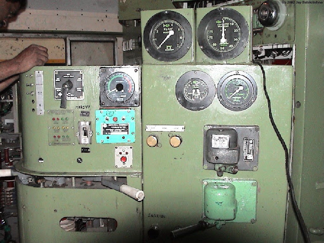
                  Here is a picture of the ALCO Loco control panel consisting of many Relays and circuit breakers.


                  and here is the pic., of the leading cab and, driver's control panel of ALCO WDM Diesel Electric Locomotive. .


                  Last edited by psr; 08-13-2012, 04:06 PM.
                  When Was The Last Time,You Did Something For The First Time.

                  Comment


                  • #84
                    We will now look briefly on the Inititaion of ALCO Diesel Electric Engine and the various stages of development done by Indian Railway Research Design &Standards Organistaion(RDSO).The first batch of ALCO engines came into India in 1961 with a confirmed Technology Transfer from ALCO, on all apects of the Engine. Diesel Locomotive Works( DLW) was formed in Varanasi specifically for the Tech., Transfer and subsequent implementation , Building, and Development of ALCO engine.In all 4,650 Locomotives were built by DLW of which 4,000 are main line Diesel Locomotives , used mainly in Freight and Passenger Trains.This consist of 12 and 16 Cylinder engines.

                    For the sake of the implementation, and R&D,... a dedicated Test Bed Facility with Four active units were made by RDSO.Each test cell has its own microprocessor controlled data acquisition and control systems and Video Display Unit (VDU)for pressure, temperature and other parameters. Various transducers relay the information from the test engines to the microprocessor based test commander for further processing with the help of sophisticated software.
                    Each test cell has an instrumentation catering to 60 to 120 pressure / temperature transducers along with sophisticated equipments like gravimetric fuel balance for measurement of fuel consumption and the equipment for measurement of air flow.
                    Below is the engine test bed with Data acquisition PC and data logging Multi Interface...


                    These test beds have also been provided with High Speed Data Acquisition System having the capability to acquire data from the engine at the frequency of 100 MHz, 16 channels of analog data can be accessed simultaneously from various transducers such as Cylinder pressure, Valve lift, Fuel injection pressure, Injector needle valve lift etc.

                    The following two fuel efficiency indices are popularly used on Indian Railways:
                    Fuel Consumption on 8th Notch :
                    Since the fuel consumption at 8th notch is highest and also since Locomotives run at this notch for longer duration as compared to other notches, fuel consumption at this notch is one of the important fuel efficiency index. This is measured in terms of gm / bhp - hr.
                    Fuel Consumption Over Duty Cycle.;
                    An Engine runs in the field at different notch as per requirement of speed / load of the locomotive. The notchwise percentage running of locomotive over duty cycle for passenger and freight operations of Indian Railways locomotives is as under:

                    Notch..................................... 8 ... 7 ... 6 ...5 ...4 ...3 ...2 ...1 ...Idle
                    Duty cycle in %.... Passenger..... 21 ... 6 ...4 ... 8 ..4 ...8 ...5 ...6 ...38
                    Freight ...................................22 ....7 ...5 ..3.5 .3.5 3.5 .3 .. 1.5...51
                    Last edited by psr; 08-13-2012, 04:30 PM.
                    When Was The Last Time,You Did Something For The First Time.

                    Comment


                    • #85
                      Let us look at the Improvements RDSO was able to achieve in taking the old ALCO design and making it to be the Work Horse of the Indian Railways...
                      In brief we will see how through various stages the RDSO improved the Power,Fuel Efficiency,and Dependability of the ALCO engine..
                      STAGE-I
                      During early 90s, fuel - efficient kit for original 16-cylinder DLW manufactured ALCO engines was developed,which reduced specific fuel consumption by more than 6% and lube oil consumption by about 15%. The reduction in fuel consumption at full load was from 166 gm/bhp/hr to 156 gm/bhp/hr at full load. Similarly, there was reduction in the % lube-fuel oil ratio from 1.5% to 1.27%.

                      Development of Efficient After -CoolerDevelopment of Improved TurbochargersDevelopment of 12.5 Compression Ratio Steel Cap Pistons
                      Original ALCO engines had aluminium dish top pistons. Use of high efficiency turbochargers and higher capacity fuel injection pumps, as brought out above, led to higher peak firing pressures. As aluminium pistons cannot withstand these higher firing pressures, steel cap pistons were developed. These steel cap pistons were provided with special crown profile for better combustion.

                      Steel cap pistons have additional advantages of longer life due to lesser wear of ring grooves and ability to withstand higher thermal load due to better cooling.
                      The estimated saving in fuel and lube oil consumption with use of steel cap piston is about 1.5% and 4% respectively.
                      Modification of Fuel Injection Pump
                      The original fuel injection pumps used on ALCO Engines had plunger diameter of 15 mm. The plunger diameter of the fuel injection pump was increased from 15 mm to 17 mm. This modification led to sharper fuel
                      injection i.e. injection at higher-pressure. The modification resulted in increase of peak fuel line pressure from 750 to 850 bars and, thus, improvement in the fuel efficiency.

                      Fuel Injection
                      The estimated fuel and lube oil economy with this modification is approx. 1.5% and 4% respectively...
                      Last edited by psr; 08-13-2012, 05:11 PM.
                      When Was The Last Time,You Did Something For The First Time.

                      Comment


                      • #86
                        STAGE-II
                        Fuel-efficient 2600 HP ALCO Engine was upgraded to 3100 HP by increasing the engine rpm from 1000 to 1050 rpm and introducing high efficiency turbocharger in the year 1992. Apart from upgradation, the above changes further resulted in the reduction in fuel consumption from 156 gm/bhp-hr to 153 gm/bhp-hr at 8th notch and reduction in the % lube-fuel oil ratio from 1.27% to 1.12%.
                        Development of High Efficiency Turbo Chargers
                        The High Efficiency Turbochargers available in world market were tested and optimised on 3100 HP upgraded engine. Two new designs of turbochargers, ABB VTC-304 VG-15 and GE 7S1716 (Twin discharge) were
                        introduced for 3100 HP engine.

                        There was increase in the Booster pressure with the use of above turbos from 1.6 to 1.9 bars. The speed of rotor at rated power also increased to 27000 rpm against 23000 rpm of Stage-I
                        turbochargers. A comparison between the turbochargers used in the two stages is given below:
                        Stages............................................ ... Stage-I............................ Stage-II
                        Technology-wise classification
                        of turbochargers..................................Eff icient........................ High efficiency
                        Turbo models used by RDS............. Napier NA295 IR ..........GE 7S1716..ABB VTC-304 VG-15
                        .............................................ABB VTC-304 VG-13..
                        Turbo over all efficiency ...........................60%.................... ............. 64%
                        Exhaust gas temp................................... 580C................................ 500C
                        Frequency of maintenance...................... 2 Years............................. 4 years
                        Salient features.............. Bearing sliding fit. Floating bush.....Bearing Sliding fit.both side thrust

                        The estimated saving in fuel and lube oil consumption with high efficiency turbocharger is approx. 1% and 4.5% respectively.
                        Introduction of Fuel Efficient Piston Rings
                        DLW engines conventionally employed a piston ring set of 5-rings having square, taper, taper, oil conformable and oil scraper configuration. Trial with piston ring set of barrel, taper, taper, oil conformable and oil conformable
                        configuration showed considerable reduction in fuel and lube oil consumption. The ring set has been named as fuel-efficient ring set.
                        Use of these rings is estimated to have reduced the fuel and lube oil consumption by approx 0.5% and 2.5% respectively.
                        Use of Multigrade Lubricating Oil
                        Single grade SAE40 lubricating oils, as recommended originally by ALCO, were being used by Indian Railways, up to 1998. Development of 20W40 multigrade oil was taken up by RDSO from 1995 onwards. These oils have
                        an additional additive called Viscosity Index Improver (VII) to reduce the change in viscosity with change in temperature. The mono-grade lube oil has a problem that its lubricating property deteriorates at higher operating
                        temperature. The lubrication of moving components was found to be better at higher temperatures with multigrade lubricating oil.

                        This behaviour of multigrade oils improves the lubrication properties at working temperatures and also results in savings of fuel. Based on results of extensive field trials of performance of multigrade oils as compared to mono-grade oils, Indian Railways switched over to use of Multigrade oil.
                        It is estimated that the fuel and lube oil saving with the use of multigrade lube oil is approximately 0.5% and 3% respectively.
                        STAGE-III
                        Literature survey showed the worldover use of 3600-3900 HP rating 16-cylinder 251 ALCO engines by Montreal Locomotive Works and Bombardier Corporation. Since M/s GETS, USA are the present holders of ALCO 251 technology, M/s. GE Transportation System, India was consulted, who agreed to associate in the project of 3600 HP upgradation by extending all possible assistance for engine configuration build-up and subsequent testing.
                        The 3100 HP ALCO Engines has, thus, been upgraded in association with M/s. GE Transportation System, India to 3300 HP in the year 2001 and to 3600 HP in 2002. The fuel consumption of the upgraded ALCO engines was also further reduced from 153 gm/bhp-hr to 150 gm/bhp-hr on top notch. Similarly, there was reduction in the % lube-fuel oil ratio from 1.12% to 1%.
                        With Upgradation of power to 3600 HP, BMEP increases by 16% over that at 3100 HP and it would result in corresponding increase in cylinder peak firing pressure and exhaust gas temperatures with the same engine configuration. Hence, there was a need of a suitable configuration to limit these critical parameters.

                        Following limits of critical parameters were fixed for the development:
                        i. Mechanical Load: Average peak firing pressure <1950 psi.
                        ii. Thermal Load: Exhaust gas temperature at turbine inlet <550 C.
                        iii. Specific Fuel Consumption: SFC at rated power <156 gm/bhp-hr.
                        iv. Surge Margin: >15%.
                        v. Boost pressure <2.2 bar.

                        and .....Introduction of New Generation Turbochargers.
                        Last edited by psr; 08-13-2012, 05:41 PM.
                        When Was The Last Time,You Did Something For The First Time.

                        Comment


                        • #87
                          Wonderful!Cant ask for a more informative thread! I have just glanced your thread and I hope to understand the concepts you have put forward, it may take ages for me! I see the hard-work you have put in to collect all these details! Will definitely be an eye opener for people who look forward to know about this topic. I have traveled in Bullet trains in Japan but have never given a thought about the concrete ballasts or the pneumatic suspensions etc you have mentioned. Now i recall those moments, i have seen and it makes sense too . Have lots of doubts but i would prefer to ask all those in 'person'.
                          Rx is a Phoenix!!! It always rise from ashes!!

                          Comment


                          • #88
                            Originally posted by dpak89 View Post
                            Wonderful!Cant ask for a more informative thread! I have just glanced your thread and I hope to understand the concepts you have put forward, it may take ages for me! I see the hard-work you have put in to collect all these details! Will definitely be an eye opener for people who look forward to know about this topic. I have traveled in Bullet trains in Japan but have never given a thought about the concrete ballasts or the pneumatic suspensions etc you have mentioned. Now i recall those moments, i have seen and it makes sense too . Have lots of doubts but i would prefer to ask all those in 'person'.
                            Glad you find the thread interesting and useful....I am actually condensing what I had learnt over many Years, and only the main areas are being discussed here....Depending on specific input from members the thread can explore more in depth ...after the Electric locomotives we will be touching upon Mag Lev which had been proposed for the Delhi Metro...You can post your doubts here or in "Person"..
                            Last edited by psr; 06-25-2012, 05:05 PM.
                            When Was The Last Time,You Did Something For The First Time.

                            Comment


                            • #89
                              Introduction of New Generation TurbochargersDevelopment of Stiffer Unit Cam Shaft
                              For generation of higher horsepower with improved fuel efficiency, fuel cam lobe design needed change for still sharper fuel injection. A new design of camshaft with modified profile of fuel cam lobe was developed. This
                              design was called Stiffer Unit Camshaft. Peak fuel line pressure of 1100 bars was achieved with this camshaft.
                              This camshaft was strengthened to take up the increased stress due to increased fuel line pressure. Other design improvements were also incorporated for longer life and easy maintenance of camshaft. Accessories like FP Support, Push Rod Lifter, Cross-Head Lifter etc. were also required to be redesigned to suit this camshaft.
                              The estimated saving in fuel and lube oil consumption using stiffer camshaft is approx. 0.5% and 3% respectively.
                              Development of Plus cylinder head
                              STAGE-IV

                              This stage consists of the technological improvements, where fuel saving on the locomotive engines have been achieved on the test bed but yet to be implemented in the field. Fuel and lube oil consumption of DLW manufactured ALCO engines have been further reduced by more than 2% and 6% with these modifications.
                              Electronic Fuel Injection System:Double Helix Fuel Injection PumpCONCLUSIONS
                              Last edited by psr; 08-13-2012, 06:06 PM.
                              When Was The Last Time,You Did Something For The First Time.

                              Comment


                              • #90
                                Apart from the improvements on the Engine itself, other improvements were also undertaken in a phased manner by IR on the ALCO Locomotive.
                                1. Changing from DC Traction Motor to AC motors
                                2. Changing Traction Motor mounting from Bush type swing arm, to Roller Bearing swing arm.
                                3. Undertaking Enamel Baking of Traction Motor Insulation for reliability.
                                4. Increasing the square area of Engine Coolant radiator for better heat management.
                                5. Implementation of Engine Oil Radiator, and subsequently increasing it's square area to enable better oil cooling.
                                6. Implementing bigger Radiator fans for both Coolant and Oil radiators for improved thermal management.
                                7. Implementing Dynamic Braking(DBR) with two sets of Resistor banks for braking from higher speed and lower speeds.
                                8. Shifting DBR to top position of engine and cooling with high RPM Fans.
                                9. Simplified Braking to decrease brake line clutter.
                                10. Installation of Microprocessor Control System for the entire LOCO for improvement in Efficiency , Management,and Monitoring.

                                Here is the approximate costing of parts and improvement implementation...

                                PART DESCRIPTION ........................ COST EACH..

                                1. ALCO DIESEL POWER PACK................. 1 Crore
                                2. Co-Co BOGIE ................................. 16 LAKHS
                                3. MODIFICATION OF ROLLER
                                SUSPENSION BEARING FOR.................... 15 LAKHS
                                TRACTION MOTOR
                                4 .ENGINE BLOCKS............................. 22.5 LAKHS
                                5. PLATE TYPE OIL COOLERS ................ 1.4 LAKHS
                                6. BHEL TRACTION MOTORS(DC)..............19 LAKHS
                                7. ENGINE COOLANT RADIATOR ............. 4.5 LAKHS
                                8. REPLACING MECHANICAL
                                GOVERNER WITH
                                MICROPROCESSOR CONTROLLED............... 6 LAKHS
                                9. Microprocessor based Control System
                                with resetting VCD, Event ......................32 LAKHS
                                Recorder, Remote Monitoring etc.,
                                10. Turbo Super Charger .........................15 Lakhs
                                11. A.C. Motors for Dust exhaust +
                                Crank Case + Fuel Pump .........................1.7 Lakhs
                                12. Air Filters....................................... 2.6 Lakhs
                                13. Self cleaning OIL filters .................... 4.0 Lakhs
                                14. AC-AC Traction Motor.........................30 Lakhs
                                15. Computer Controlled Brake System........18 Lakhs
                                16. Dynamic Braking System...................11.5 Lakhs

                                With this post the info on ALCO is coming to an end from my side.....

                                I will now wait for 2 days for Queries before moving on to GM EMD's GT46PAC diesel Loco..ie., Indian Railways WDP4 Diesel Electric Locos..
                                Last edited by psr; 06-27-2012, 02:37 PM.
                                When Was The Last Time,You Did Something For The First Time.

                                Comment

                                Working...
                                X