.
Announcement
Collapse
No announcement yet.
An INTRO to Locomotives..Steam /Diesel Electric / Electric.
Collapse
This is a sticky topic.
X
X
-
As of 2006 Electrification of most tracks were completed and hence as the more efficient mode of Locomotives were the Electric ones, Trains were run on Electric power...Sadly after 2009 the electric generation became less compared to demand and power cuts became more and long in time.Hence Diesels were pressed into service.Trains run directly by the board(Rajdhani,Shatabthi etc.,) are mostly run on Electric/Diesel Loco power depending on terrain so that their timing and running will continue, even when the train has to pass through areas where power cut will be in Vogue.Added to that if there is derailment, the Loco will invariably snap the overhead line , and it is a time consuming precision work to restore it..Under such times there is no alternative but to run with Diesel Loco...Such running of trains by Diesel Locos where Overhead lines are energized is called Diesel under wire.Originally posted by dpak89 View PostSir do you mean that only 20% of routes in India is operated by Fossil fuels currently ?
.
Taking all this into consideration IR has slowed down it's Track electrification programme from 5,200 Kms for 10 years to 2,600 Kms for 10 years ,and preference now is to run Electric Loco mainly in Dense Traffic area only.
Whenever Power situation improves The Electric Locos will be preferred over the Diesel.Last edited by psr; 07-03-2012, 05:11 PM.When Was The Last Time,You Did Something For The First Time.
Comment
-
There are two types of arguments for and against the Electric Locomotive compared to the Diesel Loco..
Most of the time the efficiency of the Electric Locomotive is said to be above 90% while the diesels are just 40~60% depending on their maintenance and age.
A new Emerging Outlook actually proves the Electric Locos to be less than Diesel in efficiency..the point of contention is that the Electric Loco draws power from overhead line and in converting it to Locomotion losses are only 10%....but the motive power of Electrical energy is mostly by Coal which gives very less energy conversion efficiency(remember Steam Locos)..Similarly a Hydel or Atomic Electrical energy production is less efficient in that heat is used to boil water into Steam ,which in turn runs a turbine to produce electricity....
So for truly calculating the electric Loco's efficiency, it's motive power generation should also be taken into account,...just like in Diesel Locos,which are stand alone generators of it's own Energy Needs...
Here is a Energy Efficiency Evaluation done by a Govt., owned Central Electricity Authority(CEA)and it's Assessment report...
Mode of Traction... Energy consumed.......... Energy consumed in KCAL......Relative Energy Index
............................per 1000 GTKM
Pass – Diesel................. 4.82................................. 42252 ........................ 1.0
Pass – Electric .............. 20.6................................. 66892......................... 1.58
Goods – Diesel .............. 2.96 ................................ 25948......................... 1.0
Goods – Electric............. 8.28 ................................ 26887......................... 1.04
So 1 Kg of High Speed Diesel used in Diesel Engine Traction =10,500 Kilo Calories.
1 KWH of electricity requires =2952 Kilo Callories...
This is the All India average Heat Rate in KCAL/KWH..
AUTHORITY For the Calculation..CEA figures.
So the Electric Traction is now proven to be less efficient than Diesel Locomotive if the Electric Power Generation is also taken into consideration.
This report and it's findings are influencing the IR's decision making ,in further Electrification of Tracks through India.
With already proven and improved Diesel Locos on Track,and it's manufacturing cost also becoming less with total indigenisation and volume, the future looks to be Diesel's domain.
Every 4,000 HP Diesel Loco saves 3 MW power on the power grid,otherwise used by a electric Loco.
Every 6,000 HP diesel saves 5 MW on the grid
It is the power used by approximately 1,500 homes...
After the CAG and CEA evaluation reports,of 1999-2000 and ,2009-2010 IR is now putting the Track electrification on go slow and increasing it's Diesel nos.
Last edited by psr; 07-03-2012, 07:20 PM.When Was The Last Time,You Did Something For The First Time.
Comment
-
We will now have a look at the Electric Locomotives of Indian railways.....
IR started with battery powered Locos at initial stage ,and only about 4 were put in service. The charging,limited power ,etc., made it undependable for regular passenger or goods movement and so it remained as an experimental effort only.
Later on the Locos were imported from England and Japan and so AC/DC dual Locos came into service in India...
We will now have a look at the initial DC locos that were in service with IR...
WCM-1....Manufactured by English Electric / Vulcan Foundry. Auxiliaries from Westinghouse. The first electrics with the now familiar Co-Co wheel arrangement to be used in India. They are characterized by their large size and unusually long hoods. The position of the entrance doors is also unusual, being not at the sides of the cabin, but through an entrance in the middle of the loco body side. Introduced in 1954, several were rebuilt in 1968. They were used on superfast trains such as the Indrayani Exp. and the Deccan Queen (?) until the 1990's. They were rarely used for freight. Air brakes for loco, and regenerative braking. Vacuum train brakes. Three different series-parallel motor combinations are available, as well as weak field operation. MU operation not possible.
WCM-2.....Manufactured by English Electric / Vulcan Foundry. Auxiliaries by Westinghouse (compressor, etc.) and North-Boyce (exhauster).Slightly smaller than the WCM-1, but with normally positioned entrance doors, these were initially built to run on the 3kV DC sections in the Calcutta area. They were rendered obsolete when still quite new when the Calcutta area was converted to 25kV AC.
The RDSO Lucknow modified them to work on 1.5kV DC without loss of power, and they were subsequently moved to the Bombay VT - Poona - Igatpuri area. Built in 1956-57, several were still in service until the 1980s.
WCM-3......Built by Hitachi. Auxiliaries by Westinghouse and North Boyce.Built in 1957-58, the smallest of the WCM series, also built for the 3kV Calcutta area and later converted to run on 1.5kV DC. Only three were built, nos. 20073-5, all now withdrawn. The WCM-3 units were characterized, apart from their dimunitive size, by separate light enclosures for the parking / marker lights (next to the headlight) and the tail lamps (just above the buffers). Later used mostly for freight. Three series-parallel motor combinations, and weak field. Air brakes for loco, vacuum train brakes.
WCM-4....... Built by Hitachi. Auxiliaries by Westinghouse and North Boyce. Built in 1960, larger and more powerful versions of the WCM-3, with normal light enclosures. Initially used to haul superfasts and other express trains, but relegated to freight operations due to technical difficulties.
These are the only WCM series locos to be used almost exclusively for freight duties (despite the M=mixed classification). Several were fitted with CBC couplers. These are also the last imported engines to come with bonnets (noses) at either end. Only seven of these units were built. Three series-parallel motor combinations, and weak field operation. Air brakes and regenerative braking for loco, vacuum brakes for train.
WCM-5 .......Built by Chittaranjan Locomotive to RDSO's design . Auxiliaries by Westinghouse and North Boyce. Built in 1962, these are India's first indigenously designed DC electrics. Similar to the WCM-4 locomotives in traction motor arrangement, etc. The first was named 'Lokamanya'. In the WCM series, these are the first to use half-collector pantographs.
There is a wide variation in the side window grille profiles, and very few of these units look alike. Several are fitted with CBC couplers. Mostly used for passenger duties. The series is withdrawn , but one has been offered to the National Rail Museum (this is probably the one later reported to be at CLW [2/05]).] Two are still in use (departmental use, etc.), homed at Kalyan, and several decommissioned examples are also at Kalyan.
WCM-6 ........ Built in 1996 by CLW, to RDSO's specifications. AC auxiliaries, underslung compressor, Siemens static converter, Elgi compressor. Used for light freight duties, especially on the Kalyan-Karjat section. Only two of these were built (#20187, #20188), perhaps because CR preferred the WCAM-3 instead.
One was seriously damaged in a fire, but was restored by the Kalyan loco shed. For a time [1999] it appears that they were used mostly for shunting duties around Bombay (Byculla yard, etc.). But both have been spotted hauling passenger trains (Diva - Panvel route, Kasara, and around Bombay. Also thought to be used for banking operations up to Lonavala. They have high-adhesion bogies similar to those on the WAG-7. Often coupled with WCG-2 locos. Speed control by three series-parallel motor combinations and weak field operation. Air brakes for loco, vacuum train brakes.
WCG-1 (EF/1) ‘Crocodile / Krokodil’ 1925....... Rod-driven C+C electric locos supplied to the GIPR in 1928 for use on the Bombay-Poona section for heavy freights. Originally classed EF/1. The first few were made by the Swiss Locomotive Works, Winterthur, and more by the Vulcan Foundry (with electricals from Metropolitan Vickers. They had four 650 hp motors (total power often quoted as 2610hp), driving two three-axle bogies through connecting rods.
Locally they were known as "khekda" ("crab") They make a curious moaning sound when at rest, and while on the run an unusual swishing sound from the link motion can be heard. Their unusual features included an articulated body (made them ideal for use in heavily curved ghat sections). They also featured regenerative braking (Newport-Shildon, UK). They were known for their superior tractive characteristics on the ghat sections; however, the exposed link mechanisms had to be oiled very frequently in all kinds of weather.
WCG–2.......... Custom-built 4200 HP freight loco for the 1.5 KVDC section of the CR Mumbai Division. Better adhesion available through the provision of a vernier control on the starting resistance. AC auxiliaries — compressor and alternator from Kirloskar, exhauster by Northey (?), others by S F India. Air brakes for loco, and regenerative brakes; vacuum train brakes. Three series-parallel motor combinations weak field operation. Bogie design as with WDM-2.
RDSO designs, based on Japanese models but final design and manufacture was by CLW. These locos can be MU'd up to 3 units. Some units of the WCG-2 model have a different gearing ratio for banking duties and are classified WCG-2A.
WCAM–1 .........Introduced in 1975. This class of loco was generally found only in the Bombay Central - Ahmedabad section. An occasional loco has also appeared on the Bombay V.T. - Igatpuri route.
One of the single pantographs on the WCAM-1 is used in dc traction; the other one carries ac current. The two pantographs are not identical, though similar in design. Bogie design as for WDM-2, WCG-2, and WAM-4 (Alco asymmetric trimount (Co-Co) bogie with cast frames). These locos perform poorly in DC mode compared to AC mode. Originally built with vacuum brakes only, although a few (Nos. 21805, 21807, 21812, 21828, 21838, 21844, 21845, and 21850) have both vacuum and air brakes. The locos are now restricted to hauling vacuum-braked trains. Loco brakes are air brakes. They also lack dynamic brakes.
The WCAM-1 does not use a variable ratio auto-transformer in AC mode like the others; it uses a fixed-ratio transformer and rectifier bank to convert the OHE supply to 1500VDC. The design of the transformers and notches makes this a hard machine to operate, with the fusible links tending to blow often. Of the 28 notches, notches 4, 14, 21, and 28 can be used for continuous operation, although notch 4 was intended for low-speed shunting and is very ineffective. Notches 14, 21, and 28 are the terminal notches of the series, series-parallel, and parallel circuit notch sequences. In DC mode, the WCAM-1 uses resistor banks for speed control.
WCAM–2 ..........WCAM-2 locos have the same traction motors, as the WCAM-1 locos, but different circuitry and gearing. The bogies are somewhat different from those of the WCAM-1 being fabricated trimount Co-Co bogies with secondary suspension. Rated speed 105km/h in both AC and DC modes. (In trials by RDSO this loco is said to have been run at speeds up to 135km/h in AC mode.)
Almost all of these are dual-braked, but a few are equipped with air brakes only. Double-header frieghts with these locos are a common sight on the Wadala road-Kings Circle-Mahim-Bandra run. They can also be seen on the Vasai-Diva-Kalyan section which is the furthest point they operate out of WR. All the WCAM-1's and -2's are homed at Valsad shed in Gujarat.
CR's WCAM locos rarely worked in DC zones (exceptions were the CR / Bombay Port Trust's Wadala marshalling yard a portion of which has DC traction, and for hauling the Punjab Mail in the late 1970's) as they delivered very poor performance in DC mode and on CR's heavy grades. Although these locos have the same traction motors as the WAM-4 and WCAM-1, the power output from the WCAM-2 locos is higher than for the WAM-4 and WCAM-1 because in those models the traction motors are underfed (3460kVA transformer in contrast to the 5400kVA transformer for WCAM-2) and do not yield their potential maximum power. Under AC traction, the WCAM-2 locos operate with all six motors in parallel (this has been enforced by modifications to these locos), while in DC mode they also operate in the all-series and series-parallel (2S 3P, i.e., three series-pairs of motors in parallel) configurations.
WCAM–3 ............These upgraded dual-traction models deliver 4600hp in DC mode and 5000hp in AC mode, and were jointly developed by RDSO and BHEL in 1997. Components are shared with the WCAG-1 locos . They have Co-Co fabricated bogies (High-Adhesion -- shared with WCAG-1, WAG-7, WDG-2, etc.) with secondary suspension. Monocoque underframe. Air brakes are original equipment. They were originally manufactured under a BOLT (build-own-lease-transfer) contract with BHEL, and are probably still owned by BHEL rather than by IR.
Monocoque underframe. Axle-hung, nose-suspended, force ventilated, taper roller bearings Speed control by tap changers in AC mode and resistance notching in DC mode. Motors can be placed in different series-parallel combinations. Auxiliaries from Elgi, S F India, Best, Gresham & Craven, etc. Static converter from ACEC for auxiliary supply.
In DC mode, rheostatic braking by self-excitation of traction motors available until 17km/h. Elgi compressor, other auxiliaries from S F India. Rated for 105km/h in both DC and AC mode (sometimes AC mode rated speed is quoted at 110km/h). In practice, WCAM-3 locos have been known to be run at speeds up to 118km/h in regular service (e.g., hauling the Deccan Queen in DC mode). Traction motor configurations as in the WCAM-1/2 and WAM-4 (all 6 in series, 2S 3P, or all parallel -- the latter is the only one used under AC traction, enforced now by modifications to the locos).
CR uses WCAM-3 locos on Mumbai-Pune and Mumbai-Igatpuri sections which have ghat portions as well as speed restrictions of about 100km/h. Freight rakes double-headed by WCAM-3 (upgraded models) have been sighted on the ghat sections. For excellent WCAM-3 sightings and regular double-header WDM-2 tanker trains, the Kurla-Vidyavihar section is ideal.Last edited by psr; 08-13-2012, 11:00 PM.When Was The Last Time,You Did Something For The First Time.
Comment
-
Since DC power is withdrawn as Motive power for Train Traction, AC powered Locos were bought and used in IR..The DC transmission and use required very thick Conductors, which means heavy support system at more costs to implement and support, and high loss in transmission and usage.With AC transmission use of Transformers greatly reduced conductor size, upkeep,and transmission and usage losses.The Locos too would use Transformers in them to step down voltage ,improve Amperes used, and have versatile Power utilization..
We will now see the AC Locomotives in use with IR.
WAM–1......... Early 2800 hp SNCF design for 25kV AC, with ignitron rectifiers. Introduced in 1959, they were mostly deployed by ER in the Howrah-Asansol-Dhanbad-Mughalsarai section.
They were less frequently found 'upstream' in the Delhi-Kanpur-Mughalsarai section, and in the Igatpuri-Bhusaval section of the Central Railway. Mostly used for non-express passenger trains, but some were used double-headed for freight service. Some were in operation on ER (Sealdah-Lalgola passenger, etc.).
WAM-1's are significant in the history of electric traction in India as they were among the first AC electrics to run in India. Like the WAG-1's, some of their advanced features turned out to be unsuitable for Indian conditions.
Manufactured by Kraus-Maffei, Krupp, SFAC, La Brugeoise & Nivelle (50 cycles European group). Ignitron rectifiers feeding four DC traction motors accepting pulsating current input. Motors are connected to the axles by a Jacquemin drive. Speed control by tap-changer on input transformer (motors permanently wired in parallel). Superstructure mounted on bogies with pendular suspension with equalizer beams. Electricals from ACEC, AEG, Alstom, Brown Boveri, Siemens and others. B-B (monomotor bogies). Jeumont transformer (20 taps), Oerlikon exhauster, Arno rotary converter. Air loco brakes, vacuum train brakes.
- Manufacturers: Kraus-Maffei, Krupp, SFAC, La Brugeoise & Nivelle (50 cycles European group)
- Traction Motors: Siemens/ACEC/Alstom MG 710A (740hp, 1250V, 480A, 1000 rpm, weight 2750kg). Fully suspended, force-ventilated.
- Rectifiers: Four water-cooled ignitrons from SGT, each rated for 575kW / 1250V.
- Pantographs: Two Faiveley AM-12.
WAM–2..........2790hp Mitsubishi locos. The first batch of 10 locos had air brakes for the loco and vacuum train brakes, and the second batch of 26 had only vacuum brakes. These have not been retrofitted with air train brakes, hence today they haul only local passenger trains. These were used on ER, and sometimes ran all the way to New Delhi via Kanpur. They were also used double-headed for freight trains. Four traction motors permanently coupled in parallel are fed by ignitron rectifiers. Speed control is by a tap changer on the input transformer. Mitsubishi transformer, 20 taps. Oerlikon exhauster and compressor, Arno rotary converter.
- Manufacturers: Mitsubishi
- Traction Motors: Mitsubishi MB 3045-A (745hp, 725V, 815A, 1000 rpm, weight 2200kg).
- Rectifiers: Mitsubishi water-cooled ignitrons (GU 31), rated at 725V / 390A.
- Pantographs: Two Faiveley AM-12.
WAM–3......... Only two of these locos existed (both at Asansol, #20333, #20337). These are basically the same as WAM-2 locos, but with reversed pantographs and Mitsubishi traction motors from a different batch, and silicon rectifiers instead of ignitrons. They came along with the second batch of (26) WAM-2 locos. These were used to haul the Kalka Mail, Toofan Exp., Amritsar Exp. at first, and then when the WAM-4P and other variants arrived they were relegated to hauling lower priority trains such as the Sealdah-Lalgola Pass. or the Howrah-Azimgunj Pass., among others. By Jan. 2000, they were relegated to shunting duties at the Asansol shed.
- Manufacturers: Mitsubishi
- Traction Motors: Mitsubishi MB 3045-A (745hp, 725V, 815A, 1000 rpm, weight 2200kg).
- Rectifiers: Two Silicon , type SF-0C20R (725V / 2260kW), rectifier cell SR200F, weight 2400kg with auxiliaries.
- Pantographs: Two Faiveley AM-12.
WAM–4
........The problems with the WAM-1 series prompted IR to come up with better models, and after some variations, the WAM-4 model was produced, the first indigenously designed and built electric loco (first units delivered by CLW in 1970-71). They were produced until about 1997.
They use the same Alco asymmetric trimount bogies as the successful WDM-2 diesel class. These locos feature rheostatic braking, and MU capability. They have silicon rectifiers. MU operation up to 4 units possible. Air brakes for loco and vacuum train brakes fitted as original equipment. Rheostatic braking also provided. Speed control by three series-parallel motor combinations and weak field operation. Auxiliaries from Westinghouse and Kirloskar (compressors), S F India (blowers), Northey (exhauster), etc.
This class proved so successful by virtue of its ruggedness suitable for Indian conditions and simplicity of maintenance, that IR used this basic design for a number of other locos later (WCAM-1, WAG-5A, WCG-2, and some WAP models). WAM-4B's were regeared versions for freight use and many were later modified and converted to other classes .
WAM-4P locos are intended for passenger operations, with some regearing and usually allowing all-parallel operation of some or all of the traction motors. The WAM-4P loco is still among the most heavily used electric locos of IR. A single WAM-4 can generally haul up to a 24-coach passenger rake.
- Manufacturers: CLW
- Traction Motors: Alstom TAO 659 A1 (575kW, 750V). Six motors, axle-hung, nose-suspended, force-ventilated.
- Gear Ratio: 15:62 originally (and still for WAM-4 2S3P), now many variations, 21:58 being common for WAM-4 6P locos..
- Transformer: Heil BOT 3460 A, 22.5kV / 3460kVA.
- Rectifiers: Two silicon rectifier cells, 1270V / 1000A each cubicle.
- Pantographs: Two Faiveley AM-12.
- Axle load: 18.8t
- Bogies: Alco asymmetric trimount (Co-Co), same as with WDM-2, WDS-6, etc.
- Hauling capacity: 2010t
- Current Ratings: (WAM-4 6P) 1100A/10min, 750A continuous.
A new Generation of Electric Locos was designed by RDSO to cater to the many requirement of IR incorporating the latest advances in the industry.
A clear distinction between Passenger and Goods were made and Locs were accordingly re-geared for their respective loads and Tractive effort.
WAP–1 ....... Built by CLW to RDSO specifications. First in the dedicated electric passenger loco series. Production began in 1980 and the locos were at first used solely for the Howrah-Delhi Rajdhani. A single WAP-1 (#22001) was all that was needed to haul the 18-coach Rajdhani at a max. speed of 120 km/h. and an average speed of around 82km/h. Continuous power 3760hp; starting TE 22.2t, continuous TE 13.8t. Loco weight is 112.8t.
The original WAP-1 locos were modified and regeared versions of the WAM-4, originally classified WAM-4R. Rated max. speed is 130km/h (some documents suggest 140km/h). Some with Flexicoil Mark II bogies were classified WAP-1 FM II and later WAP-3. Two WAP-1 units were also converted to WAP-6. One of them, #22212, the first prototype WAP-6, was then converted to a WAP-4 and was based at Jhansi
Many remaining WAP-1's are being converted to WAP-4's by a complete retrofit including new traction motors, new transformers, etc. These upgrades do not result in the 'R' suffix in the road number that is typical for rebuilt locos. Ghaziabad shed locos arethe only ones not scheduled for such upgrades and are expected to remain as 'pure' WAP-1 units. The WAP-1E has only air brakes. Earlier WAP-1's had loco air brakes and vacuum train brakes but were retrofitted for dual train brakes. Motors are grouped in 2S-3P combination and weak field operation is available. Elgi compressors, Northey exhausters, S F India blowers. The locos were originally not designed for MU operation but were later modified to allow MU'ing.
- Manufacturers: CLW
- Traction Motors: Alstom/CLW - TAO 659 (575kW (770hp), 750V, 1095 rpm) Axle-hung, nose-suspended, force-ventilated.
- Gear Ratio: 58:21
- Transformer: BHEL type HETT-3900, 3900 kVA. 32 taps.
- Rectifiers: Two silicon rectifiers, with S18FN35 cells (by Hind Rectifier) with 64 cells per unit. 2700A/1050V.
- Axle load: 18.8t.
- Bogies: Co-Co Flexicoil (cast steel bogies); primary and secondary wheel springs with bolsters
- Pantographs: Two Faiveley AM-12.
- Current Ratings: 900A/10min
WAP–2..............Regeared versions of some WAM-2 locos, fitted into a WAP-1 shell. Bogies were improved versions of the WAM-2 bogies, allowing for somewhat higher speeds. These locos were found only on ER. On rare occasions these locos were used to haul the Howrah Raj in the early 1980s. There are thought to have been only 4 of these, and they were decommissioned in the late 1980s.
WAP–3............A variant of the WAP-1, originally classified WAP-1 FMII, produced in 1987 by CLW. There were 5 of these converted from WAP-1 locos. The first WAP-3 "Jawahar", #22005, Jan. 4, 1987) was used for the Taj Exp. for some time. Essentially the same as WAP-1 but with different Flexicoil bogies (Flexicoil Mark II for the earlier ones, and Flexicoil Mark 4 (fabricated bogies) for some of the later ones, etc.). These locos could only haul 19-coach rakes for the Rajdhani and other prestigious Express trains for which they had been designed, and further required assisting locos on moderately graded sections, and so did not meet their design goals. Max. speed 140km/h.
Note: All units have been converted back to the 'WAP-1' class (since about 1997?). #22003, #22005 were among the first to be so converted and and are still in use.
- Manufacturers: CLW
- Traction Motors: Alstom/CLW - TAO 659 (575kW (770hp), 750V, 1095 rpm) Axle-hung, nose-suspended, force-ventilated.
- Transformer: BHEL type HETT-3900, 3900 kVA. 32 taps.
- Rectifiers: Two silicon rectifiers, with S18FN35 cells (by Hind Rectifier) with 64 cells per unit. 2700A/1050V.
- Axle load: 18.8t.
- Bogies: Co-Co Fabricated bogie assembly (Flexicoil Mark II and later Mark IV; the latter are somewhat similar to Alco's HiAd bogies).
- Pantographs: Two Faiveley AM-12.
WAP–4............Variant of WAP-1 with Hitachi H5 15250 motors (built by CLW), built in 1994 to RDSO specifications. The need to run longer passenger trains (24 to 26 coaches as against the 19-coach capacity of the WAP-1 / WAP-3 locos), and also to eliminate the need for bankers in graded sections (e.g., the busy Itarsi-Nagpur section) led RDSO to consider an upgraded design of the WAP-1 loco and the WAP-4 loco design was published in November 1993. Indigenously designed, higher power rated silicon rectifiers and indigenously-designed 5400kVA transformer. Locomotive reliability is also increased by the use of Hitachi traction motors. Air brakes for loco and train. Different underframe design to handle larger buffing loads. Cast bogie, Flexicoil Mark 1 design. Weight kept to 112t by the use of aluminium plates, thinner underframe, and reducing some components such as sanders. Motors grouped in 6P combination; weak field operation possible.
New versions of these with twin-beam headlights, speed recorders and some changes to the control electronics have been rolling out . WAP-4E are most likely just regular WAP-4 locos from the Vadodara shed. The 'E' suffix is thought to come from the short-lived RDSO directive to denote all air-braked locos and is redundant with the WAP-4 locos (e.g., WAP-1E). There is speculation that some of these locomotives may have some additional features such as an electronic sensor for detecting loss of pressure in brake pipes (hence, sometimes the 'E' suffix is explained as 'electronic', although this seems unlikely). Many of these have been fitted with train-parting / pressure loss alarms, and data recorders for speed, energy consumption, etc. All the new ones have roof mounted twin beam headlights, square WAP-5 type windscreens and a digital notch repeater along with a better layout and good seats for the drivers. Some even have windshield washers. A few were provided with signalling lamps on the sides but this does not have seem to have continued with the newer units.
Although these are officially rated at 140km/h, there are reports that one or more of these have been tested by CLW at up to 169.5km/h.
Note on the traction motors : The Alstom-designed 770hp TAO motors used in the WAP-1 and WAP-3 were seen as the weak link in the reliability of the locos for passenger train use. At the time, Hitachi motors of 840hp were in use on freight locos and had very high reliability, but adapting them for use with a passenger loco proved a formidable challenge because of the weight constraints. The WAP-4 design efforts involved many modifications for weight reduction, including a lighter underframe, aluminium foil-wound transformer, and the use of aluminium chequered plates, and these have allowed the use of the heavier, but more powerful and more reliable Hitachi motors on the WAP-4 locos.
- Manufacturers: CLW
- Traction Motors: Hitachi HS15250 (630kW, 750V, 900A. 895rpm. Weight 3500kg). Axle-hung, nose-suspended, force ventilated, taper roller bearings.
- Gear Ratio: 23:58 (One loco, #22559, is said to have a 23:59 ratio.)
- Transformer: 5400kVA, 32 taps
- Rectifiers: Two silicon rectifiers,
- Axle load: 18.8t.
- Bogies: Co-Co Flexicoil Mark 1 cast bogies; primary and secondary wheel springs with bolsters
- Pantographs: Two Stone India (Calcutta) AM-12.
- Current Ratings: 1000A/10min, 900A continuous
A 24-coach (1430t) passenger rake can be accelerated to 110km/h in 338 seconds (over 6.9km) by a WAP-4; to 120km/h in 455 sec. (10.5km); and to 130km/h in 741 sec. (20.5km).
WAP–5 ..........This class started with a batch of 10 locos (#30000-30010, skipping #30008) imported from ABB / AdTranz in 1995 (Actually 11 were imported but one (#30008) was damaged by fire in transit and deemed unusable on arrival. It was then used as a bank of spare parts for the others.) These are among the few currently with IR to have an advanced design with GTO thyristor converters and 3-phase asynchronous motors. CLW has been manufacturing the motors since Feb. 24, 2000. Rated top speed is 160km/h, although in trials a WAP-5 loco is said to have been run at 184km/h. Continuous power at wheel rim is 4000kW (5450hp). A WAP-5 can take a 24-coach passenger train to 110km/h in 324 seconds. Wheel arrangement is Bo-Bo. Auxiliaries from ABB, Howden Safanco, BEHR, etc.
Although these are officially rated at 160km/h, one of these has been tested by CLW at up to 184km/h. These locos are intended for use with high-speed medium load trains such as the Rajdhani and Shatabdi trains, in contrast to the WAP-7 which is more powerful but which is intended for lower-speed haulage of heavier trains.
Other notable features of this loco are the provision of taps from the main loco transformers for hotel load, pantry loads, flexible gear coupling, wheel-mounted disc brakes, and a potential for speed enhancement to 200km/h. 78t weight. Braking systems include regenerative braking (160kN), loco disc brakes, automatic train air brakes, and a charged spring parking brake. MU operation possible with a maximum of two locos.
- Manufacturers: ABB / CLW
- Traction Motors: ABB's 6FXA 7059 3-phase squirrel cage induction motors (1150kW, 2180V, 370/450A, 1583/3147 rpm) Weight 2050kg. Forced-air ventilation, fully suspended. Torque 6930/10000Nm. 96% efficiency.
- Gear Ratio: 67:35:17. (3-stage gears)
- Transformer: ABB's LOT-7500. 7475kVA primary, 4x1450kVA secondary.
- Power Drive: Power convertor from ABB, type UW-2423-2810 with SG 3000G X H24 GTO thyristors (D 921S45 T diodes), 14 thyristors per unit (two units). Line convertor rated at 2 x 1269V @ 50Hz, with DC link voltage of 2180V. Drive convertor rated at 2180V phase to phase, 953A output current per phase, motor frequency from 0 to 160Hz.
- Axle load: 19.5t
- Bogies: Bo-Bo Henschel Flexifloat; bogie centre distance 10200mm; bogie wheel base 2800mm
- Unsprung mass per axle: 2.69t
- Pantographs: Two Stone India (Calcutta) AN-12.
- Wheel diameter: 1092mm new, 1016mm worn
- Wheel base: 13000mm
- Length over buffers: 18162mm
- Length over headstocks: 19280mm
- Body width: 3142mmn
- Cab length: 2434mm
- Pantograph locked down height: 4537mm
A 24-coach (1430t) passenger rake can be accelerated to 110km/h in 312 seconds (over 6km) by a WAP-5; to 120km/h in 402 sec. (6.9km); and to 130km/h in 556 sec. (14.2km).
WAP–6
........This class is really a variant of the WAP-4 design. One or two prototypes were built early from existing WAP-1 or WAP-4 locos without renumbering. WAP-4 #22212 (formerly a WAP-1) was the first to be converted to a WAP-6; it was provided with Flexicoil bogies and other upgrades. Later this particular loco was later converted back to a WAP-4 (and even refitted with the standard WAP-4 bogies). Curiously, it spent a long time with both class codes WAP-4 and WAP-6 on it. Later, more WAP-1 locos were regeared and provided with high-adhesion fabricated bogies (Flexicoil Mark IV) which are somewhat similar to the Alco Hi-Adhesion bogies. About 16 (perhaps more) of these were built (All in the number series 22400-22416.) Of railfan interest is the fact that some of them reveal their origins in the form of the old WAP-4 class code being still evident -- often a '6' is crudely repainted over the '4' which is still visible. 
They were intended for service at 160km/h but failed trials and were restricted to a top speed of 105km/h. They were then used for less prestigious trains such as the Amritsar Exp., Doon Exp., or Janata Expresses.
- Manufacturers: CLW
- Traction Motors: Hitachi HS15250 (See description under WAP-4.) Axle-hung, nose-suspended, force-ventilated.
- Gear Ratio: 58:23
- Transformer: CCL make, aluminium coil. 5400kVA. 32 taps.
- Rectifiers: Two silicon rectifier cubicles. 2700A/1050V.
- Axle load: 18.8t.
- Bogies: Fabricated Flexicoil Mark IV bogies.
WAP–7.......... Identical to WAG-9 with modified gear ratio (72:20) and application software. 140km/h top speed. 6125hp max. power; 6000hp continuous at wheel rim. At 123t, it is much heavier than the 78t WAP-5. Intended to haul heavier, 26-coach passenger trains and passenger/parcel mixed trains. The first one, Navkiran, #30201, which was commissioned in 2000, is homed at Gomoh
Initial models were rated at 6125hp total power and 33000 kgf (323kN) tractive effort. Modifications during continuing trials resulted in improved performance with the loco now yielding 6350hp total power and 36000 kgf (352.8kN) tractive effort. In the trial runs [7/02] the upgraded WAP-7 #30203 was shown able to take a 24-coach train to 110km/h in just 235 to 245 seconds (compare: 324 seconds for a WAP-5). Braking systems as in the WAP-5, with regenerative braking rated at 183kN in the first units and 260kN in the later ones.
Earlier trials with WAP-7 locos had yielded times around 390 seconds for the same test, which had cast doubts on the future of this loco class which was designed to perform better than the WAP-5. After some trials with the Prayagraj Exp. in early 2002, now the WAP-7 is being used to haul the 24-coach rake of ER's Poorva Exp. and will be used for other trains as well. Max. tested speed is 160km/h, rated for 140km/h.
- Manufacturers: CLW
- Traction Motors: 6FRA 6068 3-phase squirrel-cage induction motors (850kW, 2180V, 1283/2484 rpm, 270/310A. Weight 2100kg, forced-air ventilation, axle-hung, nose-suspended. Torque 6330/7140Nm. 95% efficiency.)
- Gear Ratio: 72:20
- Axle load: 20.5t
- Wheel diameter: 1092mm new, 1016mm worn
- Wheel base: 15700mm
- Bogies: Co-Co, ABB bogies; bogie wheel base 1850mm + 1850mm
- Unsprung mass per axle: 3.984t
- Length over buffers: 20562mm
- Length over headstocks: 19280mm
- Body width: 3152mmn
- Cab length: 2434mm
- Pantograph locked down height: 4525mm
A 24-coach (1430t) passenger rake can be accelerated to 110km/h in 240 seconds (over 4.7km) by a WAP-7; to 120km/h in 304 sec. (6.7km); and to 130km/h in 394 sec. (9.9km).
The WAG series of AC Electric Locomotives are same as the Passenger Locos with different Gearing for more Tractive effort for pulling Goods Train at lesser speeds...Last edited by psr; 08-13-2012, 11:04 PM.When Was The Last Time,You Did Something For The First Time.
Comment
-
Here is the circuit for Electric Locomotives runnng.The First is a simple explanation,the second is the expansion of the same, and the Third is what is in the field.
The figure shows a simple feeding system. Catenary current Ic is returned as rail current IR and earth currents IE.
This second figure shows the use of booster transformers to force return current through a separate return conductor instead of through the rails or earth. Insulated rail joints ensure that currents flow in the rails only in occupied track sections. Inductive interference is reduced since the return wire is close to and parallel to the catenary.
This third figure shows an auto-transfomer system (also known as the 3-wire system or 2x25kV system). Inductive interference is reduced as the negative phase feeder and catenary carry equal but opposite currents and are close to each other and parallel. The supply voltage to the locos can be kept close to the 25kV figure by tap changers on the autotransformers. (Note: In the autotransformer case the currents drawn do not have to be symmetric across the autotransformers on the left and right of the loco -- they can vary, as long the currents add up to half the current drawn by the loco.)Last edited by psr; 08-14-2012, 11:14 AM.When Was The Last Time,You Did Something For The First Time.
Comment
-
Here is the Block Diagram representation of the motive power tapping and usage INSIDE the Electric Locomotive..


With these info the Electric locomotive Info is drawing to a close....
I look forward to queries on ALL of the Locos, and will wait for TWO days for the same.....
At this time I wish to Gratefully Acknowledge The various Sources for the Information Shared here..
The Smithsonian Institute In US of A.
1. American Loco Motive Company
2. General Motors, EMD .
3. R D S O Indian Railways
4. Diesel Locomotive Works Varanasi, & Patiala
5. Chitharanjan Locomotive works
6. Vulcan Locomotive works England
7. ALCO WORLD.... ROLF STUMPF
8. WIKIPEDIA..
Last but not the least, and one of the most important factual information site
IRFCA........Indian Railways Fan Club Association...
after TWO days, we will Look up Mag Lev.Last edited by psr; 08-14-2012, 11:16 AM.When Was The Last Time,You Did Something For The First Time.
Comment
-
Magnetic levitation transport
We will now look at the New emerging Technology of Magnetic Levitation Transport....
MagLev System relies on electromagnets..Electromagnetism is magnetism produced by an electric current. The basic idea behind electromagnets are that you can create a magnetic field by running an electric current through a conductor (like a wire). When it is twisted into a coil and its ends are connected to a voltage source (like a battery), the magnetic field through the center of the coil will have north and south poles, same as a permanent magnet. The Levitation System uses the attraction forces of electromagnets. With electromagnets, the magnetic fields can be turned on or off, and the current flowing through the coiled conductor can even be reversed, switching the electomagnetic field's polarity.

The Motor Principle
When a conductor carrying a current is in an external magnetic field perpendicular to the conductor, a force perpendicular to the conductor and the external magnetic field will be exerted on the conductor.

The definition of the ampere is described with the motor principle. One ampere is defined as the amount of current, which produces a force of 2 X 10⁻⁷ newtons per metre of conductor when it flows through two straight parallel conductors a metre apart in a vaccum.
Examples of electric devices that operate on the motor principle are analog electric meters such as voltmeters, ammeters and galvanometers. In the case of MagLevs, important applications of the motor principle include an electric motor and the train. An electric motor consists of a permanent magnet (stator) which produces an external magnetic field and a conductor coiled to form an electromagnet as the armature (rotor) which is free to rotate within the external magnetic field. The armature is connected to a voltage source through brushes and a commutator, while the rotor in a MagLev is directly wired to the train because the rotor doesn't move in relation to the train.
The speed of a motor's rotation depends on the strength of the external magnetic field from the permanent magnet and the armature's electromagnetic field strength, which is determined by the number of coils, the amount of current flowing through it and its magnetic permeability and the load to the shaft. Note, when the conductor of a motor is not supplied with a current and when the shaft is moved by an external force, a current will flow out from the conductor. This is the effect of an electric generator. It's because a current is induced when the rotor is moved inside the magnetic field of the stator. A MagLev uses the same principle for charging up its onboard batteries. That is, the cable windings moving in a magnetic field induce a current for the onboard batteries.
A MagLev is constantly kept afloat by electromagnets on the track (also called a guideway) and on the train's underside. As we all know, the opposing polarities of magnets are attracted to each other and the same polarities oppose each other. So a MagLev would be levitated with the track's and the train's magnets facing each other on the opposing sides.
There are many different MagLev systems being developed...


The most successful Mag Lev train is the Trans Rapid in Germany..The system of levitation and drive used is the Electromagnetic Type.

This system uses electromagnetic suspension technology (EMS) and it works on the concept that electromagnetic forces attract to a metal or another electromagnet when they face each other with the opposing polarities. Another system under development uses electrodynamic suspension technology (EDS) and it works on the concept of repulsive magnetic forces when electromagnets face each other with the same polarities. The EDS system uses superconductors cooled with liquid helium, and it's still in the experimental stage with many technical difficulties to be overcome. For starters, the train can't not be levitated at speeds less than 100 kilometres per hour and the magnetic field intensity inside the train is about 1000 times higher than that of the Transrapid System. Also, the super-cooled conductors are really expensive and the unregulated levitation causes rough rides on the train. So far, the Transrapid system is the only one commercially available. It's a more comfortable and safer system in terms of regulated levitation and the magnetic field intensity inside the passenger compartment. Its intensity is comparable to the earth's magnetic field and far below the field intensity of a hair dryer, an electric drill or a sewing machine. Since the Transrapid system has already been proven successful.
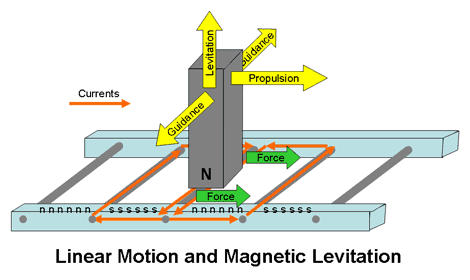
Briefly, in this system, the train and the track each have a set of electromagnets for levitation. The track has another set to keep the train positioned properly and to guide the train along. These guidance electromagnets keep the train from straying off track. Finally, another set of electromagnets built into the track and the train generate a electromagnetic travelling field that pushes the vehicle forward. There are two major systems in operation in a MagLev: the Levitation System and the Propulsion System .
1) The Levitation System
Support electromagnets built into the undercarriage and along the entire length of the train pull it up to the guideway electromagnets, which are called ferromagnetic reaction rails. The guidance magnets placed on each side of the train keep it centered along the track and guide the train along. All the electromagnets are controlled electronically in a precise manner. It ensures the train is always levitated at a distance of 8 to 10 mm from the guideway even when it isn't moving. This levitation system is powered by onboard batteries, which are charged up by the linear generator when the train travels. The generator consists of additional cable windings integrated in the levitation electromagnets. The induced current of the generator during driving uses the propulsion magnetic field's harmonic waves, which are due to the side effects of the grooves of the long stator so the charging up process does not consume the useful propulsion magnetic field. The train can rely on this battery power for up to one hour without an external power source. The levitation system is independent from the propulsion system.
2) The Propulsion System
For propulsion and braking of a MagLev, a long electromagnetic stator is installed underneath both sides of the guideway facing the train's support electromagnets, which resemble a motor's rotor. The construction of this system looks like the stator of a rotating motor was cut open and stretched along the guideway undersides and the rotor part is built into the undercarriage of a train.
The three-phase winded stator generates an electromagnetic travelling field and moves the train when it is supplied with an alternating current. The electronmagnetic field from the support electromagnets (rotor) pulls it along. The magnetic field direction and speed of the stator and the rotor are synchronized. The MagLev's speed can vary from standstill to full operating speed by simply adjusting the frequency of the alternating current. To bring the train to a full stop, the direction of the travelling field is reversed. Even during braking, there isn't any mechanical contact between the stator and the rotor. Instead of consuming energy, the Transrapid system acts as a generator, converting the breaking energy into electricity, which can be used elsewhere. The TransRapid is in use in Germany and China, ..Japan had also successfully deployed the EDS MagLev,and had experimented and successfully run a MagLev with super conductor Technology...By 1994 MagLev trains were doing above 400 kmph.....
Here is an American patented system...


Last edited by psr; 08-14-2012, 11:58 AM.When Was The Last Time,You Did Something For The First Time.
Comment
-
Magnetic levitation transport
Pros and cons of different technologies
Each implementation of the magnetic levitation principle for train-type travel involves advantages and disadvantages.
EMS (Electromagnetic suspension) Magnetic fields inside and outside the vehicle are less than EDS; proven, commercially available technology that can attain very high speeds (500 km/h (310 mph)); no wheels or secondary propulsion system needed. The separation between the vehicle and the guideway must be constantly monitored and corrected by computer systems to avoid collision due to the unstable nature of electromagnetic attraction; due to the system's inherent instability and the required constant corrections by outside systems, vibration issues may occur.
EDS (Electrodynamic suspension) Onboard magnets and large margin between rail and train enable highest recorded train speeds (581 km/h (361 mph)) and heavy load capacity; has demonstrated (December 2005) successful operations using high-temperature superconductors in its onboard magnets, cooled with inexpensive liquid nitrogen. Strong magnetic fields onboard the train would make the train inaccessible to passengers with pacemakers or magnetic data storage media such as hard drives and credit cards, necessitating the use of magnetic shielding; limitations on guideway inductivity limit the maximum speed of the vehicle; vehicle must be wheeled for travel at low speeds.
Inductrack System (Permanent Magnet EDS) Failsafe Suspension—no power required to activate magnets; Magnetic field is localized below the car; can generate enough force at low speeds (around 5 km/h (3.1 mph)) to levitate maglev train; in case of power failure cars slow down on their own safely; permanent magnets may prove more cost-effective than electromagnets. Requires either wheels or track segments that move for when the vehicle is stopped. New technology that is still under development (as of 2008) and as yet has no commercial version or full scale system prototype. Neither Inductrack nor the Superconducting EDS are able to levitate vehicles at a standstill, although Inductrack provides levitation down to a much lower speed; wheels are required for these systems. EMS systems are wheel-less.
The German Transrapid, Japanese HSST (Linimo), and Korean Rotem EMS maglevs levitate at a standstill, with electricity extracted from guideway using power rails for the latter two, and wirelessly for Transrapid. If guideway power is lost on the move, the Transrapid is still able to generate levitation down to 10 km/h (6.2 mph) speed, using the power from onboard batteries. This is not the case with the HSST and Rotem systems.
Propulsion
Some EMS systems such as HSST(, or Linimo) can provide both levitation and propulsion using an onboard linear motor. But EDS systems and some EMS systems such as Transrapid can only levitate the train using the magnets onboard, not propel it forward. As such, vehicles need some other technology for propulsion. A linear motor (propulsion coils) mounted in the track is one solution. Over long distances the cost of propulsion coils could be prohibitive.
Stability
Earnshaw's theorem shows that any combination of static magnets cannot be in a stable equilibrium. However, the various levitation systems achieve stable levitation by violating the assumptions of Earnshaw's theorem. Earnshaw's theorem assumes that the magnets are static and unchanging in field strength and that the relative permeability is constant and greater than unity everywhere. EMS systems rely on active electronic stabilization. Such systems constantly measure the bearing distance and adjust the electromagnet current accordingly. All EDS systems are moving systems (no EDS system can levitate the train unless it is in motion).
Because maglev vehicles essentially fly, stabilisation of pitch, roll and yaw is required by magnetic technology. In addition to rotation, surge (forward and backward motions), sway (sideways motion) or heave (up and down motions) can be problematic with some technologies.
If superconducting magnets are used on a train above a track made out of a permanent magnet, then the train would be locked in to its lateral position on the track. It can move linearly along the track, but not off the track.Last edited by psr; 07-06-2012, 12:09 PM.When Was The Last Time,You Did Something For The First Time.
Comment
-
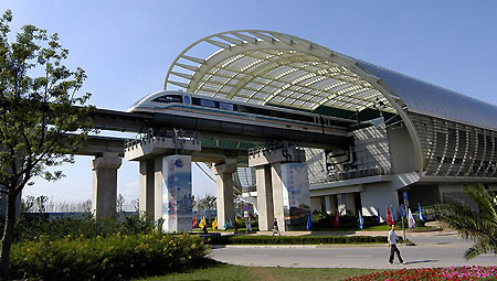
Shanghai, China

Transrapid train emerges from stylish station in Shanghai.
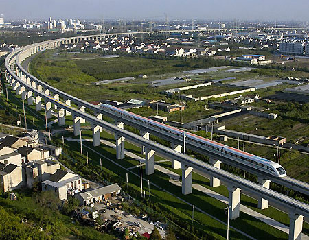
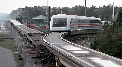
Construction began in April 2001 of the first commercial Transrapid system. Despite the fact that the maglev was the first revenue-producing point-to-point high-speed maglev in the world, the system was up and running by 2004. The 30-km line runs between Pudong Shanghai International Airport and the Shanghai Lujiazui financial district. An end-to-end ride takes about eight minutes. A world record for commercial maglev systems was set on November 12, 2003. A five-section train achieved the top speed of 501 km/h (311 mph) while another vehicle passed at 430 km/h on the adjacent track. The Transrapid in Shanghai has a design speed of over 500 km/h (310 mph) and a regular service speed of 430 km/h (267 mph). Shanghai Maglev is the fastest railway system in commercial operation in the world. Other maglev lines are under consideration in China.

History-making maglev speeds between stations.
photos courtesy of Transrapid International.
When Was The Last Time,You Did Something For The First Time.
Comment
-
Transrapid - Levitation/Guidance
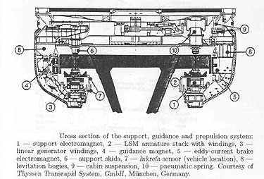
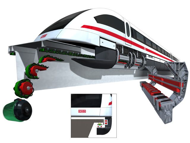
Transrapid utilizes (EMS) non-contact levitation, guidance and propulsion systems that safely and efficiently move the vehicle down a fixed guideway. Vehicle levitation is achieved by the attraction between the ferromagnetic stator packs mounted on the guideway (passive portion) and the individually controlled magnets located in the vehicle undercarriage (active portion). Lateral guidance is attained by the interaction of guidance magnets, mounted to the side of the vehicle undercarriage, and the steel guidance rails, attached to the guideway. Individual levitation and guidance magnets are grouped together and mounted continuously on both sides along the entire length of the vehicle. Likewise, system components mounted to the guideway, are fixed continuously on both sides. At stopping areas where the vehicle is set down, sliding rails on the top of the guideway support the vehicle. During operation, a highly reliable and redundant electrical control system ensures that the vehicle levitates at a constant distance of three-eighths of an inch (10 mm) from the guideway at all speeds. A secondary suspension us used with pneumatic springs.
Cutaway of TR-07 running gear.

Transrapid - Propulsion
Propulsion is accomplished through a long-stator linear synchronous motor fixed to the underside of the guideway. The concept derives from that of a standard electric motor, except that the stator and cable windings are cut and placed lengthwise along the guideway. The magnets, acting as the excitation for the motor, are mounted on the vehicle undercarriage. Therefore, instead of a rotating magnetic field, a traveling magnetic field is created by adding electrical current to the system.
Acceleration and regular braking of the vehicle is performed by the propulsion system, a synchronous longstator linear motor. In addition to these generator brakes, the braking function of the vehicle is assured by the modular eddy-current brakes. The individual eddy-current braking magnets act on the guidance rails of the guideway and guarantee the braking of the vehicle.
In the speed range 500 to 10 km/h the emergency braking function is realized by two eddy-current braking magnets per section. At speeds of less than 10 km/h, the vehicle is set down and slides on the support skids. The operation of destination braking is conducted by a safeguard computer in the vehicle which, depending on the defined brake profiles, issues control commands to the brake control units of the eddy-current brakes.
The fail-safe functioning of the eddy-current brakes is achieved by means of the modular, redundant structure and the safe fault disclosure of eight autonomous braking circuits per section
Transrapid - Power Transfer
Power for the vehicles is provided in a non-contact manner by linear generators independent of any external power. These generators deliver the entire electronic energy needed to feed all of the vehicle's power consumption. The linear generators are integrated in each single pole of the support magnets. This power is used for the hotel functions (interior lighting, HVAC, communications, etc.) Short-stator LIM-based systems need to transfer large amounts of power to run the onboard propulsion systems.
During standstill and in stations and at speeds of below 180 km/h, the required power supply for the vehicles is provided by power rails integrated in the guideway.
Transrapid - Guideway & Switching
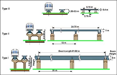
Since the guideway carries the vehicle and provides the power to the system, its precision design and fabrication are paramount to the Transrapid technology. In addition, since overall system ride comfort is directly related to the execution and quality of the guideway, adherence to specifications and tolerances is critical. Since the beginning of the operation of the Transrapid Test Facility in Emsland, Germany (TVE) in 1984, eighteen different types of guideway beams have been developed and tested. The design, installation, testing, and refinement of these guideway beam designs have led to the application beams in the Transrapid specifications.

Guideway Material Types
The guideway beam, or girder, serves two important system functions (1) to support the weight of the vehicle and transfer the corresponding loads to the ground and (2) to provide the apparatus for the mounting of the functional components. Consequently, the guideway beams must be of a suitable stiffness to maintain the system tolerances and must provide for the attachment of the functional components (guidance rails, slide rails, stator packs, motor windings, power rails, and vehicle location reference flags). These parameters have led to a standard-shaped guideway. The 'trapezoid'-shaped box cross-section provides the beam strength, while the functional components are mounted to the underside of each cantilever element of the beam. The guideway beam design allows for the flexibility of elevated, at-grade, bridge or tunnel operations.
SWITCHING
The Transrapid vehicle changes tracks using bending switches or transfer tables. Bending switches are used in mainline and off-line situations for smooth transition between tracks. They consist of welded steel, multi-span, bending beams with electro-mechanical, rack and pinion drive units mounted on every second support of the bending switch. Locking mechanisms ensure the positioning of the steel beam. Both low-speed and high-speed switches are available for use on the Transrapid system. The low-speed switch, typically used near stations and maintenance facilities, has a total beam weight of 300 tons and a total beam length of 257 feet (78 m). In the turnout position, speeds are restricted to 62 miles per hour (100 km/h), while full operating speed is allowed in the straight position. The high-speed switch, typically used on a mainline portion of a system, has a weight of 600 tons and a total beam length of 487 feet (148 m). It allows a turnout speed of 124 miles per hour (200 km/h) and permits full speed in the straight position. Bending switches are available in both two-way (switching between two tracks) and three-way (switching between three tracks) versions. The bending switches are designed for a service life of approximately a million cycles, or twenty to thirty years of typical service. One low-speed switch and two high-speed switches are currently installed at the TVE.Guideway Bending Switch:
|Transfer tables are used in off-line situations (e.g. maintenance areas) for compact access of multiple tracks. They consist of welded steel, multi-span, straight beams with electro-mechanical, rack and pinion drive units mounted on every second support of the transfer table. Locking mechanisms ensure the positioning of the steel beam. With the vehicle resting on top, the transfer table shifts laterally to access parallel segments of guideway.
Switch at Transrapid Test Facility

Last edited by psr; 08-14-2012, 12:03 PM.When Was The Last Time,You Did Something For The First Time.
Comment
-

On 22nd sept,2006 23 people lost their lives and 10 were Injured when a Transrapid MagLev train Travelling at 200 Kmph crashed into a maintenance vehicle on track.The cause was human error ....This happened in Lathen North western Germany.When Was The Last Time,You Did Something For The First Time.
Comment
-
MagLev in India
The Indian Govt is taking a hard look at MagLev in India, based on individual State Govt's,and Indian Railways proposals The first proposal came during Mr. Lallu prasad's time, but the Govt., deferred and chose to introduce Garib Rath instead. With increasing consumption of Petroleum products on Highway use, the Govt., is now having a fresh look at MagLev as not only a faster means of Travel,but also as a means of Fuel saving .This will not only save time and expense overall, but prove to be an alternate to Air Travel In India.
1. Mumbai -Pune.
1. Mumbai is planning to have its first Maglev connecting to Pune,which will take 30 minutes along the 200 km stretch . This is planned near Hinjewadi IT park in Pimple Saudagar. Pune and Mumbai has a freeway(also called as expressway) where approximately 14000 vehicles travel daily, making fuel consumption at 2,00,000 liters a day . The business proposal is to reduce the fuel consumption and promote Maglev by income from Carbon Credit Sales.
2.Mumbai – Delhi
A MagLev line project was presented to the then Indian railway minister by an American company. A line was proposed to serve between the cities of Mumbai to Delhi and the Prime Minister said that if the line project is successful the Indian government would build lines between other cities and also between Mumbai Central and CST International Airport.
3.Mumbai - Nagpur
The State of Maharashtra has also approved a feasibility study for a MagLev train between Mumbai (the commercial capital of India as well as the State government capital) and Nagpur (the second State capital) about 1,000 km (620 mi) away. It plans to connect the regions of Mumbai and Pune with Nagpur via less developed hinterland (via Ahmednagar, Beed, Latur, Nanded and Yavatmal).
4.Chennai - Bangalore - Mysore
Large and Medium Scale Industries Minister of Karnataka proposed a detailed report will be prepared and submitted by December 2012 and the project is expected to cost $26 million per kilometer of railway track. The speed of Maglev will be 350 ~400 kmph and will take 60 mins from Chennai to Bangalore, and 25 minutes Bangalore to Mysore.
5.Kochi Metro
Union Minister of State for Consumer Affairs, Food and Public Distribution K. V. Thomas proposed that Kochi Metro can adopt same technology as present in South Korea.
These are the past and present proposals of MagLev routes in India pending approval.Last edited by psr; 07-07-2012, 01:00 PM.When Was The Last Time,You Did Something For The First Time.
Comment
-
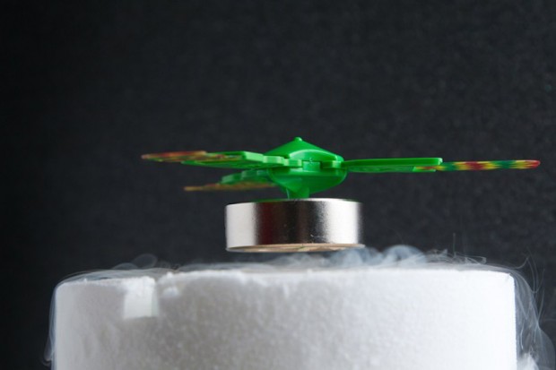
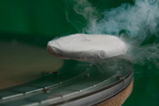
Quantum Levitation.
We will now look at a Different form of Material Levitation called Quantum Levitation....
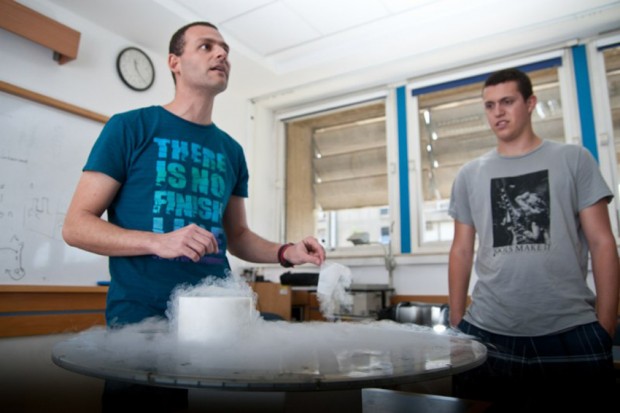
The “quantum levitation” demonstration conducted by the superconductivity group at Tel Aviv University at the 2011 Association of Science – Technology Centers’ (ASTC) annual conference in Baltimore shows that this technology has an exceptional potential.


When Was The Last Time,You Did Something For The First Time.
Comment


Comment