

And on most trains, even under normal braking some burnt smell can be noticed (i think from brake shoes) so are they overheating? How reliable/good are they?
Announcement
Collapse
No announcement yet.
An INTRO to Locomotives..Steam /Diesel Electric / Electric.
Collapse
This is a sticky topic.
X
X
-
Regarding brakes, how better those disk brakes are if compared to conventional air brake on locomotives? Similar to automobiles?
And on most trains, even under normal braking some burnt smell can be noticed (i think from brake shoes) so are they overheating? How reliable/good are they?
-
the conventional brakes work by grabbing the working surface with hard steel brake shoes, and leads to wheel aberration, the disc brake mounted on the axle does not do this...so the wheel will last longer.The burning smell is due to steel on steel braking generating heat...Originally posted by Honda_CBF View PostRegarding brakes, how better those disk brakes are if compared to conventional air brake on locomotives? Similar to automobiles?
And on most trains, even under normal braking some burnt smell can be noticed (i think from brake shoes) so are they overheating? How reliable/good are they?When Was The Last Time,You Did Something For The First Time.
Comment
-
Here are the explanations of the Two different types of brakes used in Rolling Stock of Indian Railways.
Compressed Air Brake :
The compressed air is used for obtaining brake application. The brake pipe and feed pipe run throughout the length of the coach. Brake pipe and feed pipe on consecutive coaches in the train are coupled to one another by means of respective hose couplings to form a continuous air passage from the locomotive to the rear end of the train. The compressed air is supplied to the brake pipe and feed pipe from the locomotive. The magnitude of braking force increases in steps with the corresponding reduction in brake pipe pressure and vice-versa.
Pressure :
Effective cylinder pressure = 3.8kg/cm2
Feed pipe - 6kg/cm2
Brake pipe - 5kg/cm2
Vacuum Brakes :
The vacuum brake system derives its brake force from the atmospheric pressure acting on the lower side of the piston in the vacuum brake cylinder while a vacuum is maintained above the piston. The train pipe runs throughout the length of the coach and connected with consecutive coaches by hose coupling. The vacuum is created in the train pipe and the vacuum cylinder by the ejector or exhauster mounted on the locomotive.
Pressure :
Effective pressure on piston - 0.kg/cm2
Nominal vacuum on train pipe - 510mm.When Was The Last Time,You Did Something For The First Time.
Comment
-
^ wow. Again a very well explained post. Though, still trying to understand vacuum braking system with pics by googling. If everything goes bouncer then I'll get back with questions..
Comment
-
Only recently the Train brakes have been changed to Disc brakes ...prior to that it was Sintered iron/Cast Iron shoes applying braking pressure on iron wheel.. the shoes can be removed and replaced....A picture of Sintered Iron/Cast Iron brakes shoe below.This material worked best at lower speed and needed approximately 75 Psi..Originally posted by princesirohi View Posti remember, some 20-25 years ago, i used to see the brake shoes used to have some padding, just like in automobiles, and the material used to look like wood. what was that..??

there was a phase when hardened brake shoes made of Composit material was used, ...Picture of Hardened Composit shoes below..these brakes were good at High Speed Braking but needed Twin shoes and not so good at lower speed braking..However they gave longer Wheel Life...the Air pressure needed for effective braking was also less at 45 Psi.
Last edited by psr; 08-29-2012, 05:37 PM.When Was The Last Time,You Did Something For The First Time.
Comment
-
Advantages of AIR BRAKE SYSTEM over VACUUM BRAKE SYSTEM :
Parameter .......................................AIR BRAKE................Vacuum brake
Emergency braking distance
for 4,500 tons from 65 Kmph................635 Meters...............1,100 meters
Brake power fade with use....................no fade....................upto 20 %
Pressure gradient ........................none from LOCO to........after 600 mt.
.................................................2 Km long train.............drop in Vacuum
Preparation time in ..............................< 40 minutes.........4 hours
departure yards 45 BOX carsWhen Was The Last Time,You Did Something For The First Time.
Comment
-
Even in the brake circuit There are TWO types..Originally posted by Honda_CBF View Post^ wow. Again a very well explained post. Though, still trying to understand vacuum braking system with pics by googling. If everything goes bouncer then I'll get back with questions..
1. Single Pipe Braking System
2. TWIN PIPE Braking System.When Was The Last Time,You Did Something For The First Time.
Comment
-
Single pipe brake circuit...

Twin Pipe ....

Comparison of single-pipe and twin-pipe systems
Principle of operation The operation is same as that of the twin pipe system except that the auxiliary reservoir is charged through the D.V. instead of feed pipe, since there is no feed pipe in single pipe system. The Brake pipe is charged to 5kg/cm2 by the driver's brake valve. The auxiliary reservoir is charged by the feed pipe at 6kg/cm2 through a check valve and choke. The brake cylinder is connected to the atmosphere through a hole in the D.V. when brakes are under fully released condition. To apply brakes, the driver moves automatic brake valve handle either in steps for a graduated application or in one stroke to the extreme position for emergency application. By this movement the brake pipe pressure is reduced and the pressure differenced is sensed by the D.V. against the reference pressure locked in the control reservoir. Air from the auxiliary reservoir enter the brake cylinder and the brakes are applied.At the time of release the air in the brake cylinder is vented progressively depending upon the increase in the brake pipe pressure. When the brake pipe pressure reaches 4.8kg/cm2 the brake cylinder is completely exhausted and brakes are fully released. Charging auxiliary reservoir Discontinued during brake application Uninterrupted B.C. and A.R. pressure equalisation Occurs during prolonged brake application Does not occur Release of brakes (reduction in brake cylinder pressure) Proportionate to build up of A.R pressure Auxiliary reservoir is continuously charged through feed pipe Leakage in brake cylinder during application During emergency application, feed for auxiliary reservoir from brake pipe is discontinued. Leakages in brake cylinder will therefore reduce braking force since auxiliary reservoir may not be able to equalise the leakages. Auxiliary reservoir is continuously charged through feed pipe and hence leakages in brake cylinder can be equalised even during emergency application ensuring full brake force. Colour Brake pipe - Green
Feed pipe - WhitePressure Brake pipe - 5kg/cm2 Brake pipe - 5kg/cm2
Feed pipe- 6kg/cm2Last edited by psr; 09-14-2012, 06:46 PM.When Was The Last Time,You Did Something For The First Time.
Comment
-
It is now TWO months since my last post ...
When I last saw in 14.09.2012 there were about 4,654 viewing of this thread and now i see it is 7,694..
My Heart felt Thanks for the overwhelming response from Members and Xbhp whose appreciation and encouragement is responsible for this thread's continued viewership.....
The Super Cooled Magnet levitation which was successfully tested by Japan is now being explored as the means of transport to replace the super fast trains in Japan..In 2003 Japan ran a Super Cooled ,Super conductor Train of three units at 581 Kms per hour on a Elevated track. Japan is contemplating building a SC Train and slowly replace their Bullet trains that run on conventional rails.
For this Super Cooled magnet , the Japanese use Liquid Helium to cool the windings and develop a Super Conducting magnet.The Japanese SC Maglev train uses niobium-titanium alloy magnets cooled by liquid helium to temperatures of minus 452 degrees F (minus 269 degrees C). Such chilly conditions enable a superconductive state where the electrical resistance of a material approaches zero and allow for the generation of magnetic fields bigger than those used by current Maglev trains .Last edited by psr; 11-15-2012, 12:03 PM.When Was The Last Time,You Did Something For The First Time.
Comment
-
To cool the coils to such a low temperature would require enormous amount of energy.Originally posted by psr View PostFor this Super Cooled magnet , the Japanese use Liquid Helium to cool the windings and develop a Super Conducting magnet.The Japanese SC Maglev train uses niobium-titanium alloy magnets cooled by liquid helium to temperatures of minus 452 degrees F (minus 269 degrees C). Such chilly conditions enable a superconductive state where the electrical resistance of a material approaches zero and allow for the generation of magnetic fields bigger than those used by current Maglev trains .
My question is whether the energy required to cool and maintain the temperature of coils at -269 deg C is less than the energy lost due to resistance at normal temperature ?
Leaving the top speed,will it be more energy efficient than the current maglev ?
Comment
-
If you had read my posts in earlier pages, i had discussed about Quantum Levitation...Certain materials form Magnetic flux tubes and levitate at temperatures below 185 C...So the power to levitate becomes near zero in levitation coils, and zero losses in coil Excitation.....Originally posted by shoeb2015 View PostTo cool the coils to such a low temperature would require enormous amount of energy.
My question is whether the energy required to cool and maintain the temperature of coils at -269 deg C is less than the energy lost due to resistance at normal temperature ?
Leaving the top speed,will it be more energy efficient than the current maglev ?
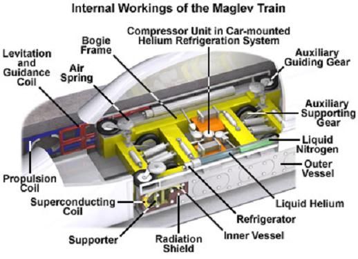
To maintain the low temperature the present Japanese design uses Liquid Helium in closed circuit being pumped through the coil structure to make it a Super Conductor...Since it is a closed loop there is no Helium lost to atmosphere. Here is a Picture of the Helium cooled super conductor Bogie of the Japanese magLev .
The Japanese MagLev uses EDS which stands for Electro Dynamic Suspension, which cannot support and levitate the bogie at speeds below 150 kms....
This means that when the train is standing in the station or is accelerating till it attains 150 Kms speed , true levitation will not occur and the bogie will use wheels. at the center of the bogie..This also means that ,if the levitation fails at higher speeds, the Train will not crash but run on the wheels and a crash will be avoided.
Once this speed is achieved the levitation will take over and the whole bogie will lift up to 10 cms above track....here is a picture of the train, it's operation and coil configuration.

Levitation...

Guidance..

Levitation and guidance combined coils..
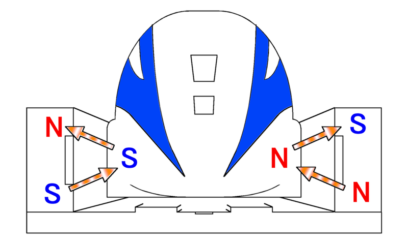
As you can see,The maglev-trains bogie has super conducting magnetic coils, and the guide ways contain levitation coils. As the train moves, its moving magnet fields create a current in the levitation coils because of the magnetic field Induction effect. These currents create a magnetic field that interacts with the magnetic field of the superconductive coils to create a force that holds up and stabilizes the train.
The current track has a series of figure-of-8 wound coils along both sides that are also cross-connected with wires that go underneath the track. When the trains run at high speed, if the magnetic field of the approach of the superconducting magnetic coils is centered then the electrical potential is balanced and no currents are induced.
However, typically, the train is running slightly below the centre of the coils due to gravity. Then the electrical potential is no longer balanced, and this causes a current that creates a reactive magnetic field that opposes the superconducting magnet's pole (in accordance with Lenz's law) and a pole above that attracts it, and so the train is pushed and pulled upwards, and prevented from falling.
Levitation coils on the guide way generate guiding and stabilizing forces also. If the train moves to the left, then currents are induced due to the cross-connections between the track coils that push and pull it straight.
Last edited by psr; 11-15-2012, 10:18 PM.When Was The Last Time,You Did Something For The First Time.
Comment
-
Here is a cross sectional view of the Helium based EDS MagLev.
here is a picture of the initial Japanese experimental Helium cooler unit used in early MagLevs...note the huge Helium tank on top of unit...
Last edited by psr; 11-21-2012, 01:06 PM.When Was The Last Time,You Did Something For The First Time.
Comment
-
Just bumped up into this thread. now i shall be glued to this.
Couple of questions sir
1) Whats the difference between Co-Co and Bo-Bo boggies
2) Do you have any information on the latest diesel engine from IR which is 5500 HP from GE. Any pics and info on when it will be put into actual use
3) Any information on IR proposed plans to manufacture higher capacity engines. Around 8000 HP diesels and 12000 HP electric ones. There were lot of advt going on for this to manufacture them with foreign collab.
Comment
-
Bo-Bo is the indication of a wheel arrangement for railway vehicles with four axles in two individual bogie, all driven by their own traction motors. It is a common wheel arrangement for modern electric and diesel locomotives .The Bo-Bo configuration allowed for higher cornering speeds due to the smaller rigid wheelbase. Furthermore it allowed better adhesion, because all the wheels were now powered. Due to the absence of frame mounted wheels no leading or trailing axles were necessary to aid cornering, reducing weight and maintenance requirements. For very heavy loads, especially in transportation of bulk goods, a single unit with this wheel arrangement tends to have too little adhesive weight to accelerate the train sufficiently fast without wheel slip.Originally posted by s_hari View PostJust bumped up into this thread. now i shall be glued to this.
Couple of questions sir
1) Whats the difference between Co-Co and Bo-Bo boggies
2) Do you have any information on the latest diesel engine from IR which is 5500 HP from GE. Any pics and info on when it will be put into actual use
3) Any information on IR proposed plans to manufacture higher capacity engines. Around 8000 HP diesels and 12000 HP electric ones. There were lot of advt going on for this to manufacture them with foreign collab.
Co-Co is a code for a Locomotive wheel arrangement with two of six-wheeled bogie with all axles powered, with a separate motor per axle. Co-Cos are most suited to freight work as the extra wheels give them good traction. They are also popular because the greater number of axles results in a lower Axle load to the track.
The working Diesel Locomotive in Service as of now, with the Maximum Horse Power is the IR WDP-4B with 4,500 HP.
This Locomotive had been fully developed by the Diesel Loco Motive Works ,at Varanasi, based on GM WDP-4(4,000 HP) Locomotive.This is a TWO STROKE Diesel Engine with Indigenous developed 32 bit Traction Control Unit and IGBT Switchers....
The Maximum HP in Diesel Traction proposed is 6,000 HP, and RDSO is working on it.
On Electric Traction we have the WAP-7 which is the highest HP rated Locomotive with 6,350 HP.
All the above said Locomotives are with Co-Co configuration.
Go to Page 10 , and onwards for details on WDP-4 class of Diesel locos.
Here are some images to give clear understanding on the different powered wheel arrangements in locomotives...


Hope this helpsLast edited by psr; 11-24-2012, 11:17 AM.When Was The Last Time,You Did Something For The First Time.
Comment


Comment