


 Tweet
Tweet
Originally posted by dux
View Post
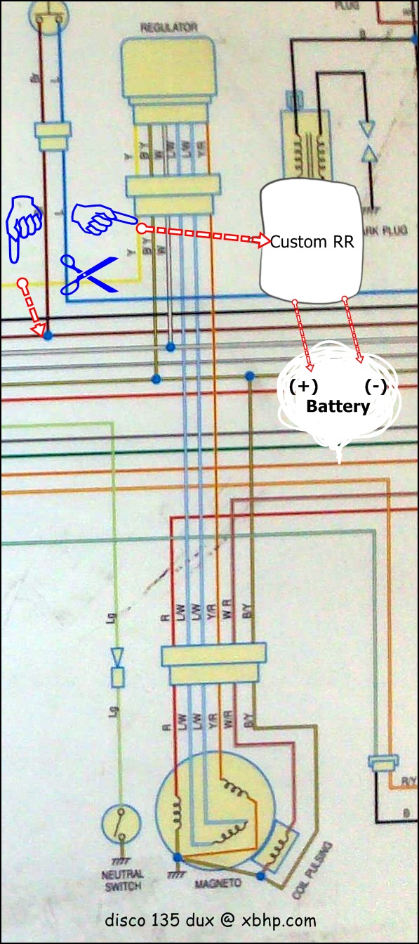
Cut the yellow wire emerging from RR
take the yellow wire (from RR end) & feed it to your custom rectifier
take a point of the chasis & feed it to the custom rectifier
directly connect the two output wires to the battery +ve & -ve.
now, connect the remaining free end of the yellow wire (that goes to the headlight) to the brown wire (locate near starter switch) & you're done

you won't need the DC change-over relay, skip that.


Comment