Since '02 xBhp is different things to different people. From a close knit national community of bikers to India's only motorcycling lifestyle magazine and a place to make like-minded biker friends. Join us

Castrol Power 1

Keep your helmet tightly strapped up.

Our Partner

Announcement

Collapse
No announcement yet.

Converted my Pulsar 150 Classic to ALL DC

Collapse
X
 
  • Filter
  • Time
  • Show
Clear All
new posts

  • Shreeni0403
    replied
    Originally posted by sajanjosepht View Post
    Obiviously its grounded as you can see from the diag. Sreeni you have to disconnect the stock RR and the batt negative terminal( we've to check the voltage and amps from the RR before connecting to the circuit) Bolt the new RR to a convient place along with the earth wire from the RR. To get a full wave bridge, u need to isolate the grounding of the light coil and take the lead out by using any of the batt charging coil wire as we dont require it any more. Hope u got it what I meant. Am I right Abhi? Dont worry about the identifying the light wires, you need to open the stator cover for isolating the grounding, that time you can have a close look and count with the higher no of poles, that is our boy. Rest of it are pretty straight, Feed these two leads of light coil straight away to the new RR. (Lead colour will be the same for the AC wires). There is one more wire ie. the +ve output connect it to the batt switch in the ignition switch. Thats it, check the voltage and current with a meter if its between 13-14.5 and the current should be more than 5A u are done. Connect the -ve terminal once u are ok with the readings. Always make sure that you are not making short lenghthed any of the wires coming out of the coil for connecting the other light coil (By doing so, any time you can go back to the stock wiring by undoing these all) Never pull out any wires from that harness as the water can easily get into the stator and u will end up in a thick soup.

    U want my email and contact no or Abhi's? Confirm it. This will work as the general electrical systems are almost alike.
    I didn't understand Head or Tail.
    I want your number and mail address, i already have Abhi's.

    Leave a comment:


  • abhijeet080808
    replied
    The stator power is not really affected. But a DC CDI will have enough power at idle rpm to fire the spark plug evenly while a AC CDI may have problem. Thats it. So, a DC CDI will result in more efficient sparks at lower rpms. But, the DC CDI depends on the battery health too.

    Sreeni, can you please confirm that Uni has DC CDI. It should be mention in the specifications part of the manual.

    According to HH website. Uni has Digital CDI! Who knows what that is!

    Leave a comment:


  • sajjt
    replied
    Originally posted by abhijeet080808 View Post
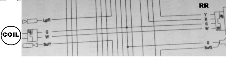
    The thing to the right of the coil is the pulsar coil for ignition, to the left is the freaking neutral indicator. And this is a DC CDI.

    Sreeni has shown me this diag before too. I told him at that time that this is not from an Uni. He tells me its from his manual. Now, Uni has a freaking DC CDI?! No way!

    And, in case of my wiring, I used 2 separate thicker wires from the 2 ends of the coil. Did not use any stock wires.

    And, oh, he is asking for your contact details!
    Yeah right, I figured out after ur tip, thanks Abhi. If its from his mannual we've to accept it. What are the pros and cons of AC/DC CDI's? Beeing a DC CDI, stator will've more power than AC types? due to the absence of AC coil for CDI?

    Sreeni, have u tried to start ur bike without batt by kicker? I think its possible if RR is present.

    Oh really? let'm say

    Leave a comment:


  • abhijeet080808
    replied
    The thing to the right of the coil is the pulsar coil for ignition, to the left is the freaking neutral indicator. And this is a DC CDI.

    Sreeni has shown me this diag before too. I told him at that time that this is not from an Uni. He tells me its from his manual. Now, Uni has a freaking DC CDI?! No way!

    And, in case of my wiring, I used 2 separate thicker wires from the 2 ends of the coil. Did not use any stock wires.

    And, oh, he is asking for your contact details!

    Leave a comment:


  • sajjt
    replied
    Originally posted by abhijeet080808 View Post
    This bike has a single stator coil. No separate AC, DC at the coil. (Look at the diag). Only the RR unit does that separation. So, you will need a separate extra wire.
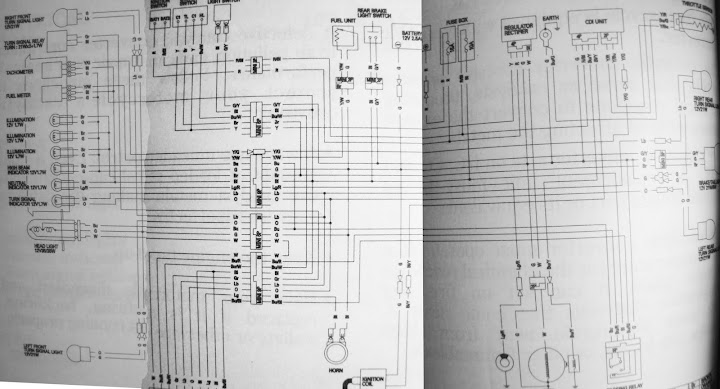
    Diag is not full and clear so I cant figure out correctly. Then wats next to the magneto coil (wire from magneto indicated as light) See the full diag, stator sec. pulse coil to CDI (DC CDI!! this wont start without a batt like bulls?) the left most, center coil is the batt coil I hope, and the third coil shown separatly is named as light. See that? Take a zoom view.
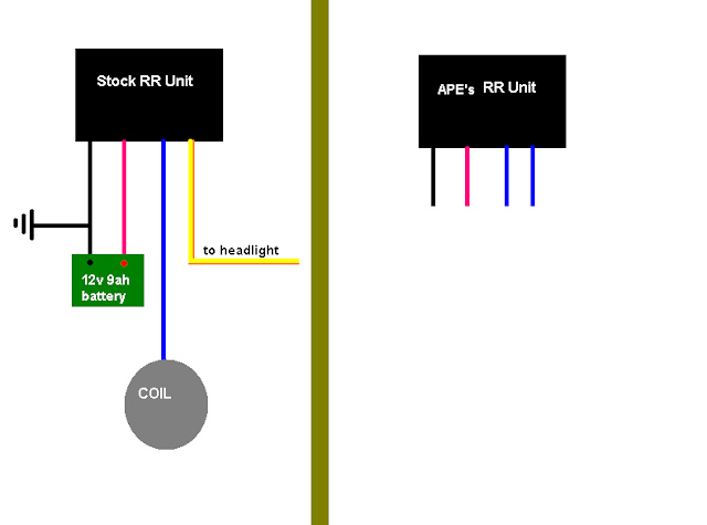
    How did u take out the coil lead out and routed to RR?, I checked with the harness, the black wire to the RR was grounded within the harness. Evenif you ungrounded and using the stock harness to connect the new RR, in effect its grounded. Thus I took a seperate wire from the coil socket directly to the RR.

    Leave a comment:


  • abhijeet080808
    replied
    Originally posted by sajanjosepht View Post
    Obiviously its grounded as you can see from the diag. Sreeni you have to disconnect the stock RR and the batt negative terminal( we've to check the voltage and amps from the RR before connecting to the circuit) Bolt the new RR to a convient place along with the earth wire from the RR. To get a full wave bridge, u need to isolate the grounding of the light coil and take the lead out by using any of the batt charging coil wire as we dont require it any more. Hope u got it what I meant. Am I right Abhi? Dont worry about the identifying the light wires, you need to open the stator cover for isolating the grounding, that time you can have a close look and count with the higher no of poles, that is our boy. Rest of it are pretty straight, Feed these two leads of light coil straight away to the new RR. (Lead colour will be the same for the AC wires). There is one more wire ie. the +ve output connect it to the batt switch in the ignition switch. Thats it, check the voltage and current with a meter if its between 13-14.5 and the current should be more than 5A u are done. Connect the -ve terminal once u are ok with the readings. Always make sure that you are not making short lenghthed any of the wires coming out of the coil for connecting the other light coil (By doing so, any time you can go back to the stock wiring by undoing these all) Never pull out any wires from that harness as the water can easily get into the stator and u will end up in a thick soup.

    U want my email and contact no or Abhi's? Confirm it. This will work as the general electrical systems are almost alike.
    This bike has a single stator coil. No separate AC, DC at the coil. (Look at the diag). Only the RR unit does that separation. So, you will need a separate extra wire.

    Leave a comment:


  • sajjt
    replied
    Originally posted by abhijeet080808 View Post
    ^^ Hey, there are 2 wires, G and W from the coil. In you MS paint diagram, it has only one wire. Is the G wire grounded?
    Obiviously its grounded as you can see from the diag. Sreeni you have to disconnect the stock RR and the batt negative terminal( we've to check the voltage and amps from the RR before connecting to the circuit) Bolt the new RR to a convient place along with the earth wire from the RR. To get a full wave bridge, u need to isolate the grounding of the light coil and take the lead out by using any of the batt charging coil wire as we dont require it any more. Hope u got it what I meant. Am I right Abhi? Dont worry about the identifying the light wires, you need to open the stator cover for isolating the grounding, that time you can have a close look and count with the higher no of poles, that is our boy. Rest of it are pretty straight, Feed these two leads of light coil straight away to the new RR. (Lead colour will be the same for the AC wires). There is one more wire ie. the +ve output connect it to the batt switch in the ignition switch. Thats it, check the voltage and current with a meter if its between 13-14.5 and the current should be more than 5A u are done. Connect the -ve terminal once u are ok with the readings. Always make sure that you are not making short lenghthed any of the wires coming out of the coil for connecting the other light coil (By doing so, any time you can go back to the stock wiring by undoing these all) Never pull out any wires from that harness as the water can easily get into the stator and u will end up in a thick soup.

    U want my email and contact no or Abhi's? Confirm it. This will work as the general electrical systems are almost alike.
    Last edited by sajjt; 10-16-2009, 05:22 PM.

    Leave a comment:


  • abhijeet080808
    replied
    ^^ Hey, there are 2 wires, G and W from the coil. In you MS paint diagram, it has only one wire. Is the G wire grounded?

    Edit : I guess so! Y is AC o/p, R is DC o/p at the RR unit. IMO, the G needs to be ungrounded from the stator coil plate. And another wire needs to be used for the second connection from the coil. Let is be B.

    Now, as for the connections, B, W will be input to the RR unit. And there will be 2 output. One is grounded. The other should be connected to Y as well as R.
    Last edited by abhijeet080808; 10-16-2009, 04:50 PM.

    Leave a comment:


  • Shreeni0403
    replied
    Originally posted by sajanjosepht View Post
    Abhi, you need more infos on what? I've detailed everything I've done on my earlier post. Anything specific?
    YES, I have specific doubts

    I am posting the Unicorn wiring diagram and a image which for which i used MSPAINT. That shows how the setup is in Unicorn now. Edit and repost, how should i connect it. Also plz PM me your contact number and email address

    RR Unit (U reply here)


    RR Unit


    Unicorn Wiring (Full)

    Leave a comment:


  • abhijeet080808
    replied
    Originally posted by kauria View Post
    Ok, So, as per your last reply, I should disconnect all the new setup I did in my bike and use this custom rectifier in place. Disconnect the AC line from the rectifier which feed the headlight at stock condition, and route it through custom rectifier to make it DC and then connect it to the headlight wire. So, in this case this custom rectifier will not provide any extra charge to battery and only the headlight will receive constant DC power, without flickering. This way my battery will get normal load and the horn & CDI acts normally. Correct me if any thing wrong.

    No, no. Connect the h/l to battery just as you are doing now. But, connect the custom rectifier to the h/l AC wire which is now idle. The output from the rectifier also goes to the battery, Thus, the AC line can charge the battery now.

    But will I be able to use 55/60 in this new setup? Because the AC power was for only 35/35 bulb and the tale light and console. I have already converted the tell lamp and the console to direct battery and they are all LED. So the only load is headlight. After doing this conversation previously I tried using a 55/60 through the AC, the light was very poor at idle and was not in its full potential even in high RPM.

    In my bike, I could run a 60/55W with LED tail light and console lights. Even, you should be able to do the same. Just try it out and see. You should also convert the pilot lights to LEDs to save some power.

    My TVS mechanic also suggests me that he will use a KB100 rectifier to convert the AC headlight current to DC and put it in the battery for extra charge. This way my horn will also work fine. He also suggest me to do it first as the AC current for headlight is in no use now and will damage the stator soon. Just ask him that if a generator generates x amount of current and I didn’t use any light & fan with it, what happen to the generated current, will it harm the generator, no reply from him.

    This is what I have suggested too. Use the AC current to power the battery. If you want, use KB100 rectifier. Another member here has found the Minidor 3 wheeler rectifier to be the best. And it is tried and tested. And now, you will not have to make a custom rectifier, so less problems in implementing the set up. And no nothing will be harmed due to excess supply as long as the voltage at the battery is below 14V.

    I am bit confused now. Which option should I go for, My motto is to use a 55/60 bulb without degrading the performance of the bike or the horn. Please suggest something.
    My replies in bold.

    Leave a comment:


  • sajjt
    replied
    Originally posted by kauria View Post
    Ok, So, as per your last reply, I should disconnect all the new setup I did in my bike and use this custom rectifier in place. Disconnect the AC line from the rectifier which feed the headlight at stock condition, and route it through custom rectifier to make it DC and then connect it to the headlight wire. So, in this case this custom rectifier will not provide any extra charge to battery and only the headlight will receive constant DC power, without flickering. This way my battery will get normal load and the horn & CDI acts normally. Correct me if any thing wrong.

    But will I be able to use 55/60 in this new setup? Because the AC power was for only 35/35 bulb and the tale light and console. I have already converted the tell lamp and the console to direct battery and they are all LED. So the only load is headlight. After doing this conversation previously I tried using a 55/60 through the AC, the light was very poor at idle and was not in its full potential even in high RPM.


    I am bit confused now. Which option should I go for, My motto is to use a 55/60 bulb without degrading the performance of the bike or the horn. Please suggest something.
    Use of custom RR is to boost the batt charging, else, u could use the stock RR. If u want more power from the stock coil, u've to sacrifice some existing load by using LED to console lighting. Or go for stator rewinding to make it a 100W. Flicker free lighting is only from DC lighting but the brightness will be more with AC lighting as the Stock RR restricts full current and volt to maintain batt health.

    There are lot of fools who doesnt know what they are doing atleast. Dont listen to thoses idiots and judge urself with logic and act accordingly. A KB100 RR is supposed to feed a batt of 2.5A, so think about it before going for it. I think you should go through these forums from the first to get a an outline about these.

    Leave a comment:


  • kauria
    replied
    Originally posted by abhijeet080808 View Post
    The custom rectifier converts AC to DC. So, now you can use 35W HID.

    60/55W can work. Just that you will have to try and see if TVS electricals are strong enough. If RTR uses DC CDI, performance can potentially decrease if the battery discharges badly.

    If you want 60/55, and do not mind dimming at idle, use LEDs in place of tail lamp and see. That will save about 10W. Else, try this rectifier and see.
    Ok, So, as per your last reply, I should disconnect all the new setup I did in my bike and use this custom rectifier in place. Disconnect the AC line from the rectifier which feed the headlight at stock condition, and route it through custom rectifier to make it DC and then connect it to the headlight wire. So, in this case this custom rectifier will not provide any extra charge to battery and only the headlight will receive constant DC power, without flickering. This way my battery will get normal load and the horn & CDI acts normally. Correct me if any thing wrong.

    But will I be able to use 55/60 in this new setup? Because the AC power was for only 35/35 bulb and the tale light and console. I have already converted the tell lamp and the console to direct battery and they are all LED. So the only load is headlight. After doing this conversation previously I tried using a 55/60 through the AC, the light was very poor at idle and was not in its full potential even in high RPM.


    I am bit confused now. Which option should I go for, My motto is to use a 55/60 bulb without degrading the performance of the bike or the horn. Please suggest something.

    Leave a comment:


  • sajjt
    replied
    Originally posted by abhijeet080808 View Post
    I have removed the green coating by using acetone. (Nail polish remover) And, its blue LEDs here.

    For resistors, see ledcalc.com. Blue is very catchy, white is classy. And, it is the mobile camera. Everything is visible!
    Thanks ya, ledcalc.com is very useful.

    U've a PM

    Leave a comment:


  • abhijeet080808
    replied
    I have removed the green coating by using acetone. (Nail polish remover) And, its blue LEDs here.

    For resistors, see ledcalc.com. Blue is very catchy, white is classy. And, it is the mobile camera. Everything is visible!

    Leave a comment:


  • sajjt
    replied
    Originally posted by abhijeet080808 View Post
    Ok.. but ur load is 130W and 8A supply is 8x12 = 96W.

    About the resistor values, tell me what colour LEDs do you want to use?


    I sanded the top of each LED flat and glues using feviquik. One LED below 0, 20, 40, 60 etc..

    Abhi, I was just calculating the old setup, now you've to deduct the 65W from as I've replaced 100/90 with 35W HID. And am not an expert like you in this, all I know is everything are fine now and me too

    Does the colour matters or size and nos? I'v got green backside coating so which one u suggest? I fine with ur config of nos LEDs. Which is that blue or white? Its very cool, but I think white will be good for green back ground.

    How about the odo and trips? Nothing on that side? I feel something is required badly as the counters are not clearly visible.

    Sanding will disburse the light more evenly, I've seen some LED lamps with translucent covers like that. Right?

    Leave a comment:

Working...
X